
User Manual

Access Point Manual Page 9 of 9
SunStream Wireless, a division of Trango Systems, Inc. Copyright © 2001
THIRD STEP: CONNECTION VERIFICATION
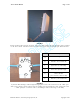
After the alignment is completed, an Ethernet cable can be connected to the “NET”
port of the Junction Box and then to a switched hub or PC network card.
NOTE: A crossover cable will be required if connecting to a PC NIC.
CAUTIONCAUTION
DO NOT APPLY POWER TO THE RADIO UNTIL THE ANTENNA IS
SECURELY ATTACHED.
M5800SB-AP-EXT Inputs and Outputs
1. POWER INPUT
The unit accepts a 10.5 – 24 Vdc power source and the standard 20 Vdc adapter
supplied should be used (supplied with SunStream part number ODU-PKIT-1).
2. ETHERNET DATA INTERFACE
Use a shielded CAT5 cable to connect the Junction Box to the Subscriber Unit radio.
Unshielded twisted pair may be used for the indoor connection to the switched hub
or PC.
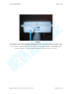
3. LED INDICATORS
These LEDs indicate when a data packet is transmitted (red) or received (green).
The yellow LED will light up and is used only during site survey.
CAUTION CAUTION
WHEN THE UNIT IS IN OPERATION, AVOID STANDING DIRECTLY IN
FRONT OF THE ANTENNA. STRONG RF FIELDS ARE PRESENT WHEN
THE TRANSMITTER IS ON.