Ffirm HD Mesh HIGH DENSITY MESH SYSTEM USER MANUAL October 25, 2006 Revision 1.
Table of Contents Preface ....................................................................................................................iii Warranty Information ...............................................................................................iii Contact Information..................................................................................................iii Section 1 Introduction .....................................................................................................
Preface This manual covers the basic configuration and installation of the HD Mesh system, and applies to the following part numbers: HD Mesh 1 HD Mesh 2 US Model International Model The HD Mesh 1/2 system consists of an outdoor rated NEMA box (R3/ IP42) that includes a 532 Mikrotik router board, a CM9 Wireless Access Point, one Omni 8dBi antenna, and 5 Trango PoE ports.
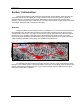
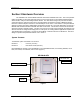
HD Mesh Node Section 1 Introduction Trango has developed a mesh architecture that maximizes up time reliability, while minimizing the constraints on actual data throughput. The Trango solution focuses the fail-safe functions at the most important element of the network, the backbone. Maintaining a robust, hi-speed and redundant mesh backbone is the most critical aspect of the network. The result is that HD Mesh provides system performance and reliability well beyond that of competing technologies.
HD Mesh Node Section 2 Hardware Overview The HD Mesh is an outdoor NEMA rated box that houses a Mikrotik 532 router. The router provides OSPF functionality on the routed ports that connect to two Trango Point to Point wireless backhaul radios which results in a layer 3 self healing wireless network. The other three Trango PoE ports can be used in conjunction with any Trango Access Point to provide wireless connections in a Point to Multipoint format.
HD Mesh Node System Radio Kits Option HDM5010-EXT: HDM5010-INT: HDM4900-INT-18: HDM4900-INT-22: HDM4900-EXT: Includes 2Atlas5010-EXT 5 GHz radios, connectorized for external antennas Includes 2 Atlas5010-INT 5 GHz radios, with integrated 23dBi antennas Includes 2 Atlas4900-INT-18 4.9GHz radios with integrated 18dBi antennas Includes 2 Atlas4900-INT-22 4.9GHz radios with integrated 22 dBi antennas Includes 2 Atlas4900-EXT 4.
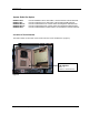
HD Mesh Node Section 2 Getting Started It is always a good idea to first provision and test the equipment on the bench before deploying them in the field. This is a particularly useful exercise for the novice user. Opening the Box Open the box by flipping up the quick release lockable latches. Quick Release Lockable Latch Pull away from box Flip Up Connections and Power Note: Improper wiring of power may power unit but may cause damage to system.
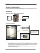
HD Mesh Node Location of RJ-45/LED Port The RJ-45 connectors for Trango Power Over Ethernet (PoE) injectors are located at the bottom of the mounting plate inside the HD Mesh box. The router ports and serial port are located at the top of the mounting plate. The PoE diagnostic LEDs are located on the face lid of the mounting plate. Functionality of the LEDs is described later in this text.
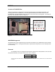
HD Mesh Node Browser Interface The HDMESH features a convenient and easy-to-use web based configuration and management tool. No additional software is needed on your computer other than a web browser. The browser interface offers limited and basic functions, although the majority can only be performed via command line interface (CLI). To use the browser interface, the following must be present: • An Ethernet (wired or wireless) connection between a PC and the HD Mesh unit.
HD Mesh Node Primary Features and Pages of the Browser Interface: Navigation Column: Each page features a navigation column that runs along the left-hand side of the page. On the bottom of the navigation column is the current status of the router including its System ID, IP address, Time, Date, CPU Utilization, Uptime, Disk Space Free, Disk Space Total, Memory Free, Memory Total, Rx, Tx, AP, Clients, and Timeout.
HD Mesh Node Winbox (GUI) Interface The HDMESH features a convenient and easy-to-use GUI interface tool. The Winbox interface offers the closest functionality to the Command Line Interface (CLI). . The Winbox interface provides a lot more functionality than the Web Interface. Winbox is improving with each release but CLI still provides the most functionality To use the Winbox, the following must be present: • An Ethernet (wired or wireless) connection between a PC and the HD Mesh unit.
HD Mesh Node Primary Features and Pages of the Winbox Interface: Menu Bar: Winbox has a menu bar that runs along the left-hand side of the page. Interface: General information of the interface, Status, Ethernet port settings and traffic. Wireless: Wireless status, Access List, Registration, Connect List, Security Profiles, and wireless settings. Bridge: Shows Bridge status, Ports in the Bridge, Filters, Broute, NAT and Hosts.
HD Mesh Node Command Line Interface The Web browser interface covers very basic features in a limited role. The command line interface (CLI) provides much more functionality, and is usually the management tool of choice for experienced users. The CLI can be accessed through Telnet or Console cable. Telnet Open a command prompt (DOS) session on your PC. Open a Telnet session by typing: telnet [ip address of router] All HD mesh units are pre-configured at the factory.
HD Mesh Node Section 3 Basic Configuration via Web Browser This section describes a few basic concepts, as well as how to configure basic settings using the Browser (HTTP) Interface. This section is written to address only the most basic steps. It is highly recommended that you visit and read Mikrotik’s website to gain an understanding of all important configuration parameters.
HD Mesh Node Port Web Configuration Clicking on the IP address of the interface will bring up the port configuration page. The port can be disabled, configured to obtain an IP address from a DHCP server, or manually configured with an IP address and Netmask. (Figure 8) Figure 8 Port Name Web Configuration Clicking on the name of the port will allow you to change the name of the port.
HD Mesh Node System Web Configuration The System page will allow you to change the password simply by clicking the password link. The ID of the HDMESH can also be changed from the system page. The unit can also be rebooted. The system page also provides you with a system RESET. (Figure 11) Note: The system reset defaults the unit completely to Mikrotik’s default configuration. You will then need to reload Trango’s default configuration.
HD Mesh Node DHCP Server Web Configuration The HD Mesh node is configured by default as a DHCP server. DHCP Services can be applied to any interface. DHCP leases are also shown on this page. The following information must be to be provided.
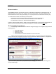
HD Mesh Node Upgrading RouterOS via Web Browser The RouterOS can be upgraded from the web browser upgrade page. The RouterOS can be downloaded from Mikrotik’s web site www.mikrotik.com Click on the UPGRADE from the navigation menu on the left side of the web page. (Figure 14) Figure 14 A window browser will open for you to select the NPK file to upload. Once the file is selected click the upload button to begin transferring the file from you computer to the router.
HD Mesh Node Once the file has been successfully uploaded to the router the upgrade and downgrade button can be used. (Figure 16) Figure 16 The upgrade procedure will log out the current web session. The process will take a few minutes for the upgrade procedure to complete. (Figure 17) Note: DO NOT POWER OFF router during this process Figure 17 To verify the upgrade procedure was successful. Log back into the router and check the version under the system page.
HD Mesh Node Section 4 Basic Configuration via Winbox This section describes how to configure basic settings using Winbox. This section is written to address only the basic steps. It is highly recommended that you visit and read Mikrotik’s website to gain an understanding of all important configuration parameters.
HD Mesh Node Configuring the Wireless Card Clicking the Wireless menu option from the menu bar will bring up the Wireless Tables. Double clicking on the wireless interface will bring up the Interface configuration menu. Once in the configuration menu there are a number of tabs General, Wireless, Data Rates, Advance and Status are just a few. For more information on settings consult Mikrotik’s website. (Figure 21 & 22) Figure 21 . There are many option that can be selected in the Wireless tab.
HD Mesh Node Configure Firewall The firewall configuration offers many options but this section will only cover creating NAT on an interface using masquerading. In the Winbox session select IP menu then Firewall menu option. This will open the Firewall Windows. (Figure 23) Figure 23 The following tabs are presented in the firewall window: Filter Rules, NAT, Mangle, Connections, and Address Lists. Select the NAT table and click on the red plus sign to open the New NAT Rule window.
HD Mesh Node Next in the New NAT Rule select the ACTION tab. The ACTION needs to be set to MASQUERADE. Click APPLY then OK and the NAT masquerade is configured. (Figure 25) Figure 25 Configuring DHCP Server By default the DHCP Server service is enabled in Trango Broadband configuration on Ether1, 2, 3, 4, 5, WLAN, and the bridge interfaces. In order to create a DHCP Server from within Winbox select IP then DHCP Server.
HD Mesh Node Clicking the Setup button in the DHCP Server window will bring up the DHCP Server Setup window. Select the interface on which to run DHCP services. (Figure 27) Figure 27 Once the interface is selected, the DHCP Address Space will need to be added. (Figure 28) This will be followed by the Gateway for DHCP Network. (Figure 29) Note The DHCP Gateway is the IP address of the interface.
HD Mesh Node The next prompt will be for the range of IP addresses to give out. This will create an IP pool automatically. (Figure 30) After the IP address range is given, a DNS server IP address is required. (Figure 31) Note: If not filled out properly the Setup will end without creating the DHCP server Figure 30 Figure 31 Lastlly the Lease Time will need to be given. The default is 3 days. The format is days: hours:minutes:seconds. If this is filled out properly a success windows will open.
HD Mesh Node Configuring OSPF OSPF stands for Open Shortest Path First. This routing protocol is the key to creating redundancy by the HD Mesh node. This Section will cover how to configure OSPF. The OSPF configuration window can be opened by selecting Routing then OSPF. (Figures 34 & 35) Figure 34 Figure 35 Create an area by clicking on the ‘area’ tab and then clicking on the red plus sign. This will open the New OSPF Area. The following information will need to be supplied.
HD Mesh Node Once the Area is created, the OSPF Networks that will be distributed in the OSPF link need to be added. In the OSPF window (Figure 35) go to the Network tab and click on the Red Plus sign. This will open the OSPF network. The Network needs to be added to include the mask. Select the Area which was created. (Figure 37) Figure 37 Now that the Area and Network have been added we need to configure which interfaces will pass OSPF information.
HD Mesh Node The final step is to configure the OSPF settings. In the Interface tab click on settings to bring up the OSPF settings windows. The setting will vary depending on the role of the router. If the router has a connection to the Internet then the following settings are recommended.
HD Mesh Node Section 5 Basic Configuration via CLI This section describes a Command Line Interface configuration. This section is written to address only the basic steps. It is highly recommended that you visit and read Mikrotik’s website www.mikrotik.com to gain an understanding of all configuration parameters. In this section you will learn the following: • • • Configure an IP address and Gateway Configure DHCP client Configure DHCP server Note: See Appendix A for more information on serial port.
HD Mesh Node Configuring IP Address via CLI Setup In the setup menu you can configure an IP address simply by supplying the interface name and the IP address with the netmask.
HD Mesh Node Configuring Gateway via CLI Setup Simply selecting an option will bring the next menu prompt. The only information needed to set the Gateway is the gateway IP address. Example of configuring the Gateway on the router your choice [press Enter to configure ip address and gateway]: a + a - add ip address * g - setup default gateway x - exit menu your choice [press Enter to setup default gateway]: g gateway: 192.168.4.254 #Adding default route /ip route add dst-address=0.0.0.0/0 gateway=192.168.4.
HD Mesh Node Configuring DHCP Server via CLI Setup Following the menu option the following information will need to be provided in order to create the DHCP Server • DHCP server interface: • DHCP address space: • gateway for DHCP network: • DHCP relay • addresses to give out: • DNS servers: • lease time: Example of a configured DHCP server. + s - setup dhcp server p - setup pppoe client t - setup pptp client * x - exit menu your choice: s dhcp server interface: ether6 dhcp address space: 192.168.0.
HD Mesh Node Section 6 Default Configuration The HD Mesh node is configured with the first 5 ports as router ports, each with their own IP address. The ports are also configured to give out DHCP IP addresses. Ports 6, 7, and 8 are configured to act as a single bridge. The bridge is configured with an IP Address and also as a DHCP server. The wireless card is configured with its own IP address and also as a DHCP Server. Port 9 is configured as a DHCP client.
HD Mesh Node Restoring Default Configuration WinBox Each router has a backup of this configuration stored in its file system. The backup file can be seen through Winbox by selecting files. The name of the backup file is “OneMESH.backup”. Select this file and click on Restore and the unit will prompt you to restore and reboot. Click on File, Select the backup file and Click on Restore. You will be prompted to confirm restore.
HD Mesh Node Restoring Default Configuration Command Line Interface The default configuration can also be reloaded via the command line. Simply login to the Mikrotik router and type the following command. System backup load name=OneMESH Example of loading default configuration. MikroTik v2.9.32 Login: admin Password: MMM MMM MMMM MMMM MMM MMMM MMM MMM MM MMM MMM MMM MMM MMM III III III III KKK KKK KKK KKK KKKKK KKK KKK KKK KKK RRRRRR RRR RRR RRRRRR RRR RRR MikroTik RouterOS 2.9.
HD Mesh Node Appendix A Serial Port The HD Mesh unit features a serial port. The serial port is useful in the event that the router cannot be accessed via TCP/IP (HTTP, Telnet, or Winbox). A Terminal Emulation program (such as HyperTerminal on the Windows operating system) can be used to access the HD Mesh’s CLI using the serial port, which is located in the top right side of the enclosure. The serial 9 pin db female connector can be used with a standard null-modem cable to manage the HD Mesh unit.
HD Mesh Node Appendix B Specifications All specifications apply to HD Mesh Node HD Mesh Node Enclosure HD Mesh Box NEMA rated outdoor enclosure Ratings NEMA 3R / IP42 Dimensions 14 in. × 12 in. × 7 in. (39.3 × 34.2 × 19.
HD Mesh Node Wireless Board 802.11a: -88 dBm @ 6 Mbps, -71 dBm @ 54 Mbps 802.11b: -95 dBm @ 1 Mbps, -90 dBm @ 11 Mbps Sensitivity 802.11g: -90 dBm @ 6 Mbps, -74 dBm @ 54 Mbps Hardware 40 bit & 108 bit WEP. Security Hardware AES-CCM Modulation 802.11b/g: DSSS (DBSP, DQPSK, CCK) OFDM techniques for data rate > 20 Mbps 802.11a: OFDM (BPSK, QPSK, 10-QAM, 64-QAM 18 dBm @ 2.4 GHz RF power output 17 dBm @ 5.8 GHz Wi-FiR WECA Compliant, FCC Part 15 (USA) * The system will use a maximum of 350 Watts.