
Installation and Maintenance Manual


Table Of Contents
- Warnings, Cautions and Notices
- Model Number Descriptions
- General Information
- ECM Application Notes
- Dimensions and Weights
- Receiving and Handling
- Pre-Installation
- Installation—Mechanical
- Installation—Piping
- Installation—Sensors
- Installation—Electrical
- ECM Overview and Setup
- Time Clock
- Wired Controllers—Communication Wiring
- Pre-Start
- Startup
- Tracer ZN520 Unit Startup
- Tracer UC400 Unit Startup
- General Information
- Fan Mode Switch Operation
- Tracer ZN520 Operation
- UC400 Controller Operation
- Tracer ZN520 Sequence of Operation
- UC400 Sequence of Operation
- Power-up Sequence (UC400)
- Random Start (UC400)
- Occupancy Modes (UC400)
- Timed Override Control (UC400)
- Zone Temperature Control (UC400)
- Discharge Air Tempering (UC400)
- Heating or Cooling Mode (UC400)
- Entering Water Temperature Sampling Function (UC400)
- Fan Operation (UC400)
- Exhaust Control (UC400)
- Valve Operation (UC400)
- Modulating Outdoor/Return Air Damper (UC400)
- Two-position Control Of A Modulating Outdoor Air Damper (UC400)
- Electric Heat Operation (UC400)
- Dehumidification Operation (UC400)
- Peer-to-peer Communication (UC400)
- Unit Protection Strategies (UC400)
- Maintenance
- Diagnostics
- Replacing ECM Components
Installation—Sensors
34 UV-SVN03F-EN
2. Verify that the sensor is set to the same address as the
receiver it is to be associated with.
3. Power the sensor by removing t
he insulation strip from
between the two batteries.
Association is autom
atically initiated between the sensor
and the receiver. When LED3 on the receiver stops
blinking, association has been established.
If the first association attempt is unsuccessful, the sensor
automatically re-attempts association with the receiver
every 10 minutes.
Note: An associated sensor that has lost communication
with the receiver will transmit an association
request every 50 minutes. You can manually
initiate association (see “Manual Association
(Wireless Controls),” p. 99”).
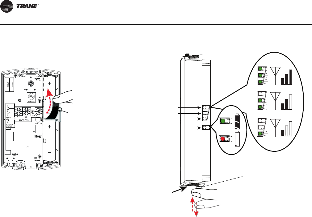
Testing Signal Strength and Battery Status
To verify that the association process was successful and
that the batteries have adequate charge:
1. Firmly press and release the Test button on the bottom
of the sensor (as illustrated below).
2. For model WZS, view LED1, LED2, and LED3 to
d
etermine the signal strength. View LED5 to determine
the battery status (see the following figure for model
WZS sensors).
Note: Th
e LEDs will turn Off after 5 seconds to
conserve battery strength.
For model WDS, determine the signal strength and
battery status by viewing the symbols on the sensor
display (see the following figure for model WDS
sensors).
3. Record the results in your commissioning statem
ent.
Note: For more information, see “Testing Signal Strength
(Wireless Controls),” p. 97 and “Testing Battery
Status (Wireless Controls),” p. 98.
LED1
LED2
LED3
LED5
Model WZS sensor
Push firmly,
then release
Test button
UV-SVN03_.book Page 34 Thursday, January 24, 2013 5:27 PM