
Installation and Maintenance Manual


Table Of Contents
- Warnings, Cautions and Notices
- Model Number Descriptions
- General Information
- ECM Application Notes
- Dimensions and Weights
- Receiving and Handling
- Pre-Installation
- Installation—Mechanical
- Installation—Piping
- Installation—Sensors
- Installation—Electrical
- ECM Overview and Setup
- Time Clock
- Wired Controllers—Communication Wiring
- Pre-Start
- Startup
- Tracer ZN520 Unit Startup
- Tracer UC400 Unit Startup
- General Information
- Fan Mode Switch Operation
- Tracer ZN520 Operation
- UC400 Controller Operation
- Tracer ZN520 Sequence of Operation
- UC400 Sequence of Operation
- Power-up Sequence (UC400)
- Random Start (UC400)
- Occupancy Modes (UC400)
- Timed Override Control (UC400)
- Zone Temperature Control (UC400)
- Discharge Air Tempering (UC400)
- Heating or Cooling Mode (UC400)
- Entering Water Temperature Sampling Function (UC400)
- Fan Operation (UC400)
- Exhaust Control (UC400)
- Valve Operation (UC400)
- Modulating Outdoor/Return Air Damper (UC400)
- Two-position Control Of A Modulating Outdoor Air Damper (UC400)
- Electric Heat Operation (UC400)
- Dehumidification Operation (UC400)
- Peer-to-peer Communication (UC400)
- Unit Protection Strategies (UC400)
- Maintenance
- Diagnostics
- Replacing ECM Components
Installation—Sensors
30 UV-SVN03F-EN
Installing Wall-Mounted Wired
Sensors
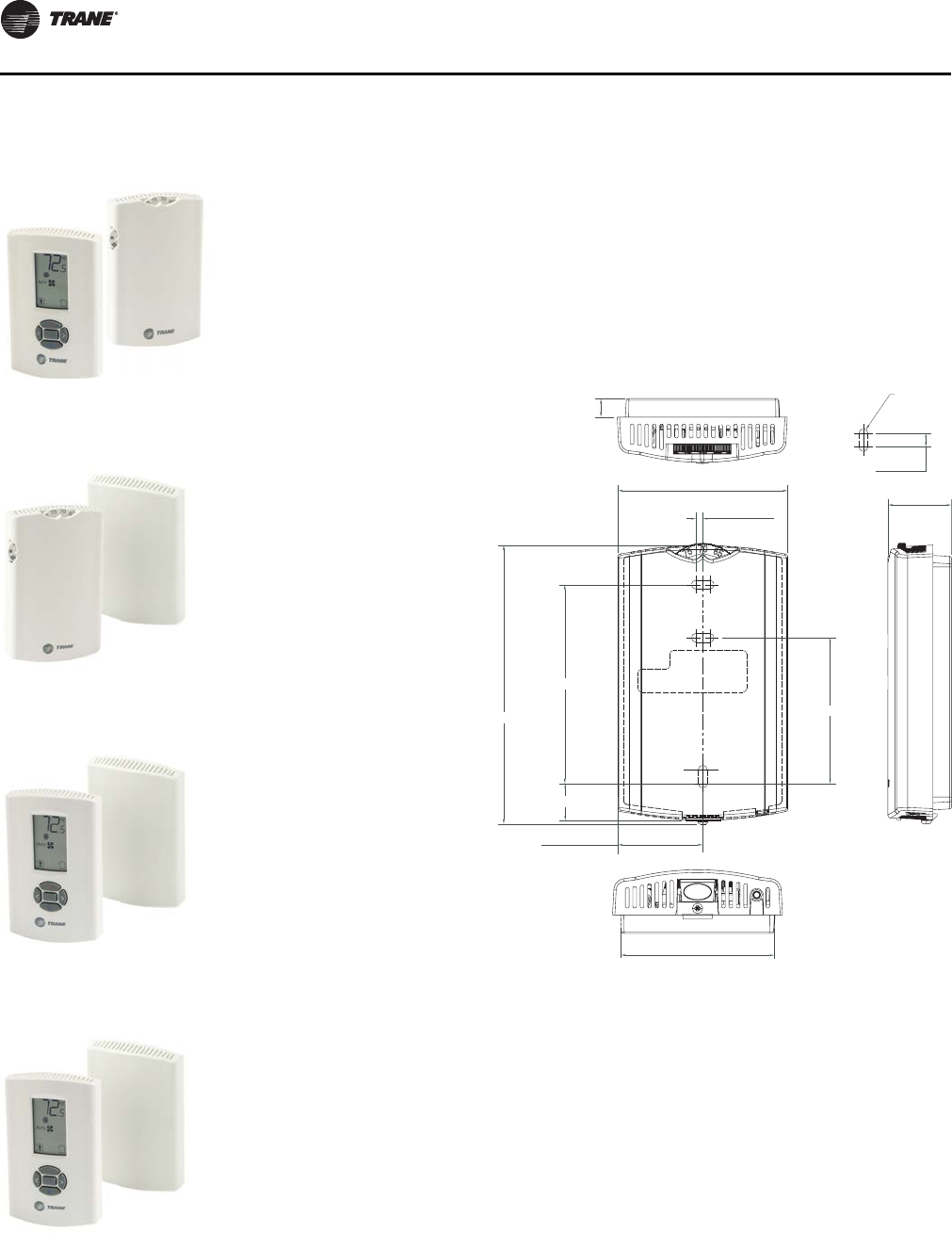
Reference the wall-mounted zone sensor dimensions in
Figure 36, p. 30. Position the sensor on an inside wall three
to five feet above the floor and at least 18 inches from the
nearest outside wall. Installing the sensor at a lower height
may give the advantage of monitoring the temperature
closer to the zone, but it also exposes the sensor to airflow
obstructions. Ensure that air flows freely over the sensor.
Sensor
When selecting a sensor location, avoid the following:
• Areas of direct sunlight
• Areas in the direct airstream of air diffusers
• Exterior walls and other walls that have a
temperature
differential between the two sides
Figure 32. Unit mtd FSS (OLH),
wall mtd display temp sensor
(SP, OCC/UNOCC, COMM)
Figure 33. Wireless temp sensor
(SP, OCC/UNOCC, OALMH, COMM)
Figure 34. Wireless temp sensor with display
(SP, OCC/UNOCC, COMM)
Figure 35. Wireless temp sensor with display
(SP, OCC/UNOCC, COMM)
X13790886-03 (wall)
X13790475-01 (unit)
X13790492-01 (wall)
X13790855-01 (unit)
X13790822-04 (wall)
X13790855-01 (unit; 3-speed)
X13790822-01 (wall)
X13790855-01 (unit; 2-speed)
Figure 36. Wall-mounted wired and wireless zone
sensor dimensions
1. 0.31 in
2. TYP R.07 in (R1.9)
3. TYP 0.24 in)
4. 2.9 in
5. 1.08 in
6. 0.12 in
7. 3.39 in
8. 4.68 in
9. 2.48 in
10. 0.63 in
11. 1.45 in
12. 2.62 in
1
2
3
4
5
6
7
8
9
0
-
=
UV-SVN03_.book Page 30 Thursday, January 24, 2013 5:27 PM