
Installation and Maintenance Manual


Table Of Contents
- Warnings, Cautions and Notices
- Model Number Descriptions
- General Information
- ECM Application Notes
- Dimensions and Weights
- Receiving and Handling
- Pre-Installation
- Installation—Mechanical
- Installation—Piping
- Installation—Sensors
- Installation—Electrical
- ECM Overview and Setup
- Time Clock
- Wired Controllers—Communication Wiring
- Pre-Start
- Startup
- Tracer ZN520 Unit Startup
- Tracer UC400 Unit Startup
- General Information
- Fan Mode Switch Operation
- Tracer ZN520 Operation
- UC400 Controller Operation
- Tracer ZN520 Sequence of Operation
- UC400 Sequence of Operation
- Power-up Sequence (UC400)
- Random Start (UC400)
- Occupancy Modes (UC400)
- Timed Override Control (UC400)
- Zone Temperature Control (UC400)
- Discharge Air Tempering (UC400)
- Heating or Cooling Mode (UC400)
- Entering Water Temperature Sampling Function (UC400)
- Fan Operation (UC400)
- Exhaust Control (UC400)
- Valve Operation (UC400)
- Modulating Outdoor/Return Air Damper (UC400)
- Two-position Control Of A Modulating Outdoor Air Damper (UC400)
- Electric Heat Operation (UC400)
- Dehumidification Operation (UC400)
- Peer-to-peer Communication (UC400)
- Unit Protection Strategies (UC400)
- Maintenance
- Diagnostics
- Replacing ECM Components
Installation—Piping
UV-SVN03F-EN 27
Wiring the Valve
A controller and a separate transformer is required to
operate each valve (see Figure 18 and Figure 19, p. 27).
Port A “open” and “closed” denote valve open and closed
positions.
The typical floating controller is an SPDT controller with a
center-off position. On a change in temperature from the
set point, the controller will close the normally open (NO)
or normally closed (NC) contacts, driving the valve to an
intermediate position until a further change at the
controller.
The valve is set between the limits of the controller to
satisfy various load requirements. In the event of power
failure, the valve will stay in the position it was in before
loss of power. When power is restored, the valve will again
respond to controller demand.
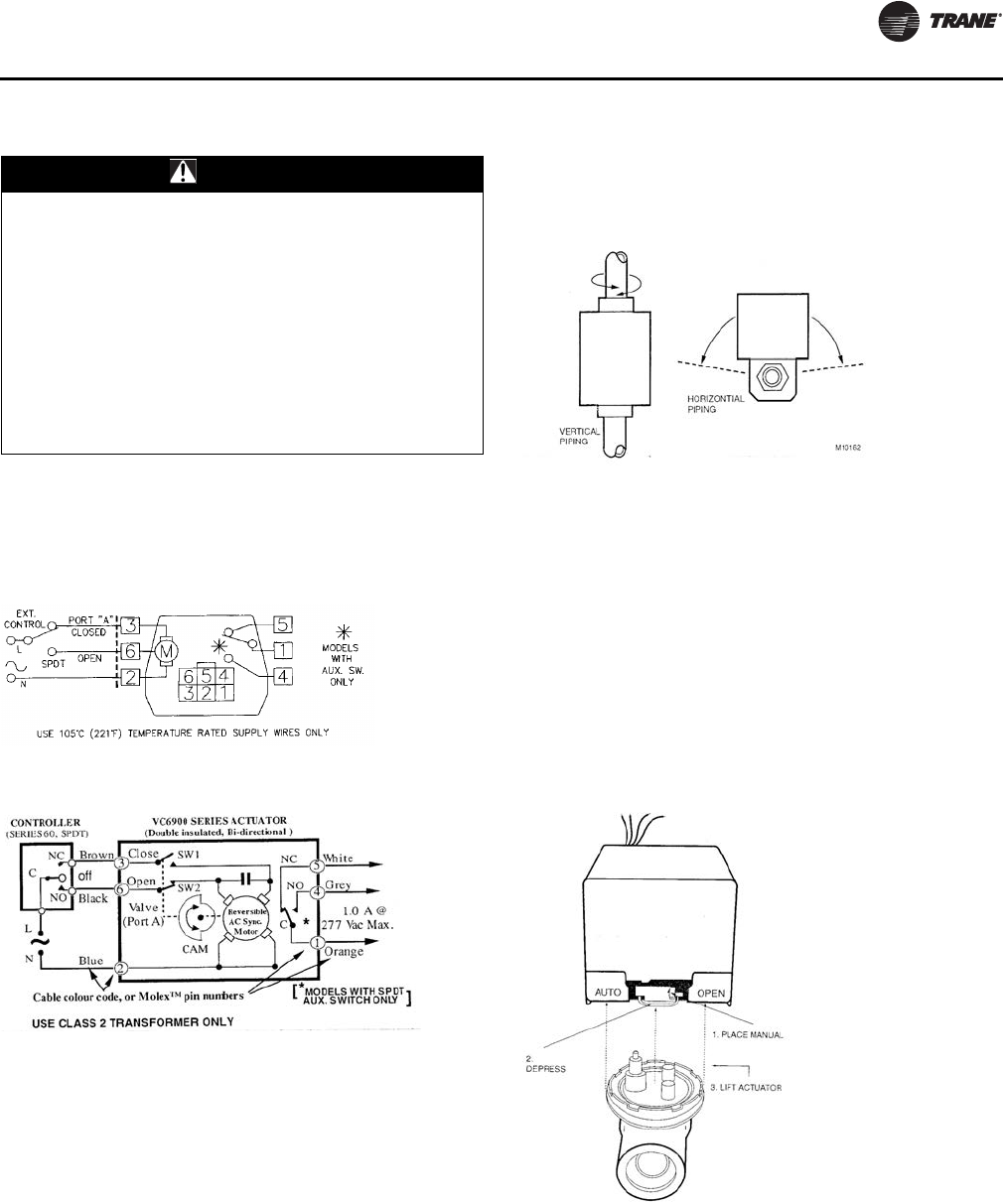
Isolation Valves Installation
The valve can be mounted in any position on a vertical line.
If the valve is mounted horizontally, the actuator must be
even with or above the center line. Make sure there is
enough room to remove actuator cover for servicing.
Mount the valve on the tube or pipe.
Note: Ensure the flow through the valve is in the direction
indicated by the arrow stamped on the valve body.
Servicing/Removal of Valves
The actuator can be removed from the valve body.
Removing the actuator is recommended if soldering is
being conducted near the valve. To remove the actuator:
1. Place the manual operating lever to the Open position
(see Figure 21, p. 27).
2. Depress the locking button and lift actuator until it
separates from the valve body.
To install the actuator
to the valve body:
3. Align the slot on the shaft of the
valve with the valve
body notch on side of body (see Figure 22, p. 28).
WARNING
Electrocution and Fire Hazards with
Improperly Installed and Grounded
Field Wiring!
Improperly installed and grounded field wiring poses
FIRE & ELECTROCUTION hazards. To avoid these
hazards, you MUST follow requirements for field wiring
installation and grounding as described in NEC and
your local/state electrical codes. All field wiring MUST
be performed by qualified personnel.
Failure to follow these requirements could result in
death or serious injury.
Figure 18. Wiring for modulating valve actuator
Figure 19. Wiring for modulating valve actuator
Figure 20. Proper mounting for isolation valves
Figure 21. Removing valve actuator
UV-SVN03_.book Page 27 Thursday, January 24, 2013 5:27 PM