
Installation and Maintenance Manual


Table Of Contents
- Warnings, Cautions and Notices
- Model Number Descriptions
- General Information
- ECM Application Notes
- Dimensions and Weights
- Receiving and Handling
- Pre-Installation
- Installation—Mechanical
- Installation—Piping
- Installation—Sensors
- Installation—Electrical
- ECM Overview and Setup
- Time Clock
- Wired Controllers—Communication Wiring
- Pre-Start
- Startup
- Tracer ZN520 Unit Startup
- Tracer UC400 Unit Startup
- General Information
- Fan Mode Switch Operation
- Tracer ZN520 Operation
- UC400 Controller Operation
- Tracer ZN520 Sequence of Operation
- UC400 Sequence of Operation
- Power-up Sequence (UC400)
- Random Start (UC400)
- Occupancy Modes (UC400)
- Timed Override Control (UC400)
- Zone Temperature Control (UC400)
- Discharge Air Tempering (UC400)
- Heating or Cooling Mode (UC400)
- Entering Water Temperature Sampling Function (UC400)
- Fan Operation (UC400)
- Exhaust Control (UC400)
- Valve Operation (UC400)
- Modulating Outdoor/Return Air Damper (UC400)
- Two-position Control Of A Modulating Outdoor Air Damper (UC400)
- Electric Heat Operation (UC400)
- Dehumidification Operation (UC400)
- Peer-to-peer Communication (UC400)
- Unit Protection Strategies (UC400)
- Maintenance
- Diagnostics
- Replacing ECM Components
Replacing ECM Components
110 UV-SVN03F-EN
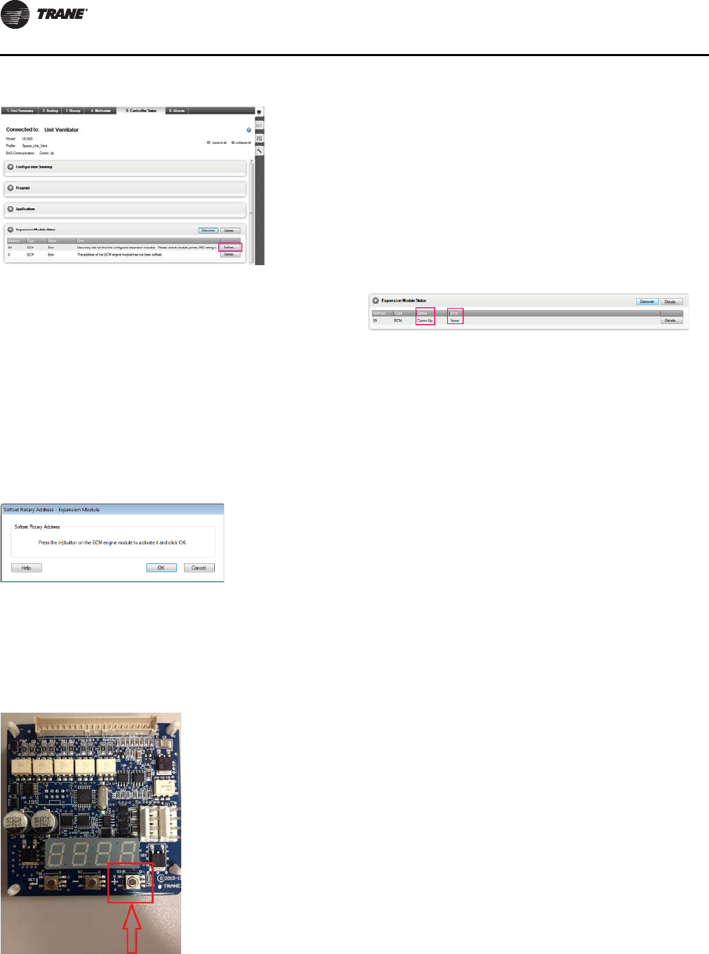
Notice one ECM type is configured at address 99, but no
ECM is found at that address. Also, notice that another
ECM has been found with an address of 0. When this
situation occurs, Tracer TU displays a Softset… button you
can use to configure the engine module address.
Complete the following steps to softset the engine module
address:
1. Cli ck the Softset… button to initiate the softest
procedure.
Tracer TU displays the Softset Rotary Address -
Expansion Module dialog box.
2. Prior to clicking OK, activate the engine module using
the (+) button on the ECM engine board in the control
box.
Once the engine module is acti
vated, the LED to the
right of the (+) button lights up.
3. Once the light has been activated, click OK on
the
Softset Rotary Address - Expansion Module dialog box
shown in Step 2.
When you click OK, Tracer TU sof
tsets the engine
module IMC address to 99 and the light on the module
will turn off.
4. Return to the Expansion Module Status box, click
Disco
ver and wait five to ten seconds for Tracer TU to
refresh the screen.
Once complete, the value in the Error column updates
to None and the Status column updates to Comm Up.
Figure 70.
Figure 71.
Figure 72.
Figure 73.
UV-SVN03_.book Page 110 Thursday, January 24, 2013 5:27 PM