Operators Guide TR200 Vertical Bypass/Non Bypass Panel Trane optimizes the performance of homes and buildings around the world. A business of Ingersoll Rand, the leader in creating and sustaining safe, comfortable and energy efficient environments, Trane offers a broad portfolio of advanced controls and HVAC systems, comprehensive building services, and parts. For more information, visit www.Trane.com.
Safety Safety WARNING EQUIPMENT HAZARD! The vertical bypass/non bypass panel contains dangerous voltages when connected to mains voltage. It is strongly recommended that all electrical work conform to the National Electrical Code (NEC) and all national and local regulations. Installation, start-up and maintenance should be performed only by qualified personnel. Failure to follow the NEC or local regulations could result in death or serious injury.
Contents Contents 1 Introduction 1.1.1 Purpose of the Manual 2-1 1.1.2 Overview 2-1 1.1.3 Typical Bypass Operation 2-1 1.2 Bypass Circuits 2-1 1.2.1 Three-contactor Bypass 2-1 1.3 Bypass Options 2-2 1.3.1 Common Run/Stop with Bypass 2-2 1.3.2 Automatic Bypass 2-2 1.3.3 Run Permissive in Bypass 2-2 1.3.4 Basic Fire Mode in Bypass 2-2 1.3.5 Advanced Fire Mode in Bypass 2-2 1.3.6 Overload Protection 2-2 1.4 Bypass Platform Configurations 2-3 1.5 Switch Mode Power Supply 2-3 1.5.
Contents 3.2.1 Lifting 4-3 3.2.2 Hoist or Overhead Lift 4-3 3.2.3 Forklift 4-3 3.2.4 Shipping Weights 4-3 3.3 Cooling 4-4 3.4 Electrical Installation 4-5 3.4.1 Component Identification & Customer Connection 4-7 3.4.2 Wire and Cable Access 4-15 3.4.3 Wire Size 4-19 3.4.4 Wire Type Rating 4-20 3.4.5 Terminal Tightening Torques 4-20 3.4.6 Input Line Connection 4-25 3.4.7 Motor Wiring 4-25 3.4.8 Grounding (Earthing) 4-26 3.4.9 Control Wiring 4-26 3.4.
Contents 6.1.5 ECB Hand/OFF/Auto 7-8 6.1.6 ECB Mode of Operation 7-8 6.1.7 Bypass Status Word Bit Examples 7-10 6.1.8 ECB Auto Bypass 7-10 6.1.9 ECB Run Permissive 7-11 6.1.10 ECB Overload 7-11 6.1.11 ECB Safety Interlock 7-12 6.1.12 ECB Common Run/Stop 7-12 6.1.13 ECB Advanced Fire Mode 7-13 6.1.14 ECB Fault Reporting 7-13 7 Start Up Troubleshooting 7.1.1 Option Panel Alarm and Warnings 8 Appendix BAS-SVX49A-EN 8-1 8-1 9-1 8.1.1 Dimensions 9-1 8.1.2 Mechanical Diagrams 9-2 8.1.
Contents BAS-SVX49A-EN
Introduction 1 Introduction 1.1.1 Purpose of the Manual This manual is intended to provide detailed information for the installation and operation of the option panel used in conjunction with a Trane variable frequency drive (VFD or drive). To enable efficient handling of the equipment, requirements are provided for installation of mechanical, electrical, control wiring, proper grounding, and environmental considerations. Pre-start and start up procedures are detailed.
Introduction Contactor Drive Mode OFF Bypass Test Mode Mode M1 Closed Open Open Closed M2 Closed Open Open Open M3 Open Open Closed Closed Table 1.1 Contactor Operation Figure 1.1 Basic Non Bypass Circuit 1.3.4 Basic Fire Mode in Bypass 1.3 Bypass Options 1.3.1 Common Run/Stop with Bypass Allows a remote signal to initiate operation in either drive control or bypass depending upon the position of the bypass selector switch. 1.3.
Introduction 1.4 Bypass Platform Configurations The two bypass platform configurations are ECB and EMB2. The features available as options with each platform are listed in Table 1.2. The ECB, also listed below, has all option features available. See 5 Electromechanical Bypass (EMB2) Operation for additional details on the EMB2 and 6 Electronically Controlled Bypass (ECB) Operation for the ECB.
Introduction the option panel door can be opened. (Bypass panel only.) • Disconnect without fuses. For user-supplied fuses option. (Bypass panel only.) • Main circuit breaker. A thermal/ magnetic current interrupt device using an ON/TRIP/OFF/RESET switch. When in the ON position, a trip fault removes power from the drive/bypass circuit and the switch moves to the TRIP setting. The switch must be moved to the RESET position momentarily after the fault has been cleared to reset the circuit breaker.
Introduction 1.6.3 Panel Configurations The TR 200 Drive Series comes in two panel enclosure types. One is the non bypass and the other is the bypass. See Table 1.3 for descriptions and available options. Non bypass Bypass Drive plus both of the following: Drive with bypass: 1. Fuses 1. Fuses 2. Disconnect 2. Disconnect/Circuit Breaker 3. Contactors 4. Power Supply 5. Control Module Table 1.
Introduction 1.6.4 Panel Voltage and Frame Ratings Table 1.4Table 1.4 defines the voltage and hp ratings of the frames sizes for the panel. See 8 Appendix for overall and mounting dimensions. Panel P2 Bypass Non Bypass (B3 - Drive) TR200 TR200 Volts VAC HP (KW) 208 & 230 7.5 (5.5) - 15 (11) 7.5 (5.5) - 15 (11) 460 & 600 15 (11) - 25 (18.5) 15 (11) - 25 (18.5) Panel P3 Bypass Non Bypass (B4 - Drive) TR200 TR200 Volts VAC HP (KW) 208 20 (15) 230 20 (15) - 25 (18.
Pre-installation 2 Pre-installation 2.1.1 Receiving Inspection Inspect the packaging and equipment closely when received. Any indication of careless handling by the carrier should be noted on the delivery receipt, especially if the equipment will not be immediately uncrated. Obtain the delivery person’s signed agreement to any noted damages for any future insurance claims. Ensure that the model number and power match the order and intended use for the drive.
Pre-installation dirt. If the unit does not have power applied to it, supply a protective covering. It is important to ensure that the components stay as clean as possible. It may be necessary to clean the interior once construction is completed. • Keep drawings and manuals accessible for detailed installation and operation instructions. It is important that the manuals be available for equipment operators. 2.
Installation 3 Installation 3.1.1 Tools Required TOOLS Spreader bar capable of lifting up to 750 lbs. In addition to the standard tool kit, the tools in Table 3.1 are recommended for installation of the option panel. Max diameter 0.5 in. Forklift, crane, hoist or other lifting device capable of handling up to 750 lbs. (Qualified device operator available for operating the equipment.
Installation 230 V AC HP (KW) UL Motor Panel (TR200) Non Bypass Main Fuse (TR200) Drive Fuse (TR200) Transformer Fuse (TR200) Current & Bypass Bussman Bussman Bussman LPJ-35-SP JJN-50 7.5 (5.5) 22 10 (7.5) 28 15 (11) 42 20 (15) 54 25 (18.5) 68 30 (22) 80 40 (30) 104 50 (37) 130 60 (45) 154 P2 P3 P4 P5 LPJ-45-SP JJN-50 LPJ-70-SP JJN-60 LPJ-90-SP JJN-80 LPJ-100-SP JJN-125 LPJ-125-SP JJN-125 LPJ-150-SP JJN-150 LPJ-200-SP JJN-200 FNQ-R-1.
Installation 3.1.3 Internal Main Panel Fuses Use only the specified fuse or an equivalent replacement for the internal main fuses. See the specifications label inside the cover of the unit for acceptable replacement main fuses. A sample of this can be seen in Table 3.6. Fuse Description Manufacturer Part Number/Size F13A & C Primary Transformer Bussmann FNQ-R-0.
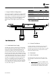
Installation Figure 3.2 Side Cooling Clearance Figure 3.1 Proper Lifting Method 3.3 Cooling • • Only mount the drive and panel vertically. • Most panels may be mounted side-by-side without additional side clearance. However, the P2 (B3 frame size) units require 1.5 in. minimum clearance between units (see Figure 3.2). • Top and bottom clearance is required for cooling (see Figure 3.3). Generally, 2 to 10 inches (50 to 250mm) minimum clearance is required, depending upon the hp (kW) of the unit.
Installation 3.4 Electrical Installation WARNING Hazardous Voltage! Disconnect all electric power, including remote disconnects before servicing. Follow proper lockout/tagout procedures to ensure the power cannot be inadvertently energized. Failure to disconnect power before servicing could result in death or serious injury. WARNING Proper Field Wiring and Grounding Required! All field wiring MUST be performed by qualified personnel.
Installation Figure 3.
Installation 3.4.1 Component Identification & Customer Connection Mechanical layout drawings are intended to provide the installer or equipment user with component identification and location for that specific unit. Figure 3.5 represents a typical layout drawing. Table 3.8 provides definitions for drawing reference designators. (Not all reference designators are shown.) Figure 3.
Installation Figure 3.6 P2 Non Bypass Mechanical Layout Diagram. See Table 3.8 for reference designator definitions.
Installation Figure 3.7 P3 Bypass Mechanical Layout Diagram. See Table 3.8 for reference designator definitions.
Installation Figure 3.8 P3 Non Bypass Mechanical Layout Diagram. See Table 3.8 for reference designator definitions.
Installation Figure 3.9 P4 Bypass Mechanical Layout Diagram. See Table 3.8 for reference designator definitions.
Installation Figure 3.10 P4 Non Bypass Mechanical Layout Diagram. See Table 3.8 for reference designator definitions.
Installation Figure 3.11 P5 Bypass Mechanical Layout Diagram. See Table 3.8 for reference designator definitions.
Installation Figure 3.12 P5 Non Bypass Mechanical Layout Diagram. See Table 3.8 for reference designator definitions.
Installation 3.4.2 Wire and Cable Access WARNING Hazardous Voltage! Disconnect all electric power, including remote disconnects before servicing. Follow proper lockout/tagout procedures to ensure the power cannot be inadvertently energized. Failure to disconnect power before servicing could result in death or serious injury. • Refer to through for wire routing and termination locations. • Removable access knockout covers are provided for cable connections (see Figure 3.13 and Figure 3.14).
Installation Figure 3.15 P2 Panel Figure 3.
Installation Figure 3.
Installation Figure 3.
Installation 3.4.3 Wire Size WARNING ELECTROCUTION AND FIRE HAZARDS WITH IMPROPERLY INSTALLED AND GROUNDED FIELD WIRING! Improperly installed and grounded field wiring poses FIRE & ELECTROCUTION hazards. To avoid these hazards, you MUST follow requirements for field wiring installation and grounding as described in the National Electrical Codes (NEC) and your local/state electrical codes. All field wiring MUST be performed by qualified personnel.
Installation 460 VAC HP (KW) UL Motor Current 15 (11) 21 20 (15) 27 25 (18.
BAS-SVX49A-EN 200 (22.5) 200 (22.5) 200 (22.5) 200 (22.5) 70 (7.9) 55 (6.2) Disconnect Switch *Note 1 124/212.4 (14/24) 88.5 (10) 88.5 (10) 40 (4.5) 40 (4.5) 40 (4.5) 16 (1.8) 16 (1.8) 16 (1.8) Torque lb-in (N-m) Fusible UL98 L1, 7 (0.8) 200 (22.5) 200 (22.5) 200 (22.5) 200 (22.5) 55 (6.2) 18 (2) 18 (2) 7 (0.8) 30 (3.3) 500 (56.5) 500 (56.5) 200 (22.5) 200 (22.5) 200 (22.5) 120 (13.5) 120 (13.5) 30 (3.3) 274 (31) 274 (31) 50 (5.6) 50 (5.6) 50 (5.6) 50 (5.
3-22 20 (15) P5 P4 P3 Table 3.12 Tightening Torques, 230 V 60 (45) 50 (37) 40 (30) 30 (22) 25 (18.5) 40 (4.5) 70 (7.9) 200 (22.5) 200 (22.5) 200 (22.5) 124 (14) 88.5 (10) 88.5 (10) 40 (4.5) 40 (4.5) 55 (6.2) 70 (7.9) 16 (1.8) 16 (1.8) 200 (22.5) 200 (22.5) 200 (22.5) 55 (6.2) 18 (2) 18 (2) 18 (2) 7 (0.8) 7 (0.8) L1, L2, & L3 Torque lb-in (N-m) 16 (1.8) (w/o Fuses) UL508A Torque lb-in (N-m) Disconnect Switch 230 V AC Motor T1, T2, & T3 Output 55 (6.2) 55 (6.
BAS-SVX49A-EN P5 Table 3.13 Tightening Torques, 460V 125 (90) 100 (75) 200 (22.5) 200 (22.5) 200 (22.5) 70 (7.9) P4 40 (4.5) 55 (6.2) 50 (37) 60 (45) 75 (55) 40 (4.5) 55 (6.2) 40 (30) 16 (1.8) 55 (6.2) 124 (14) 124 (14) 88.5 (10) 88.5 (10) 40 (4.5) 55 (6.2) 30 (22) P3 16 (1.8) 16 (1.8) 25 (18.5) 55 (6.2) 55 (6.2) P2 Output 460 VAC Input Bypass Output 200 (22.5) 200 (22.5) 200 (22.5) 55 (6.2) 18 (2) 18 (2) 18 (2) 7 (0.8) 7 (0.8) 7 (0.8) 500 (56.5) 200 (22.
3-24 P5 Table 3.14 Tightening Torques, 600V 125 (90) 100 (75) P4 200 (22.5) 200 (22.5) 70 (7.9) 55 (6.2) 60 (45) 75 (55) 55 (6.2) 55 (6.2) 40 (30) P3 30 (22) 50 (37) 55 (6.2) 55 (6.2) 25 (18.5) 55 (6.2) 20 (15) P2 Output 600 VAC Input Bypass Output 124 (14) 124 (14) 88.5 (10) 88.5 (10) 40 (4.5) 40 (4.5) 40 (4.5) 16 (1.8) 16 (1.8) 16 (1.8) 200 (22.5) 200 (22.5) 55 (6.2) 55 (6.2) 18 (2) 18 (2) 7 (.79) 7 (.79) 7 (.79) 7 (.79) 200 (22.5) 200 (22.5) 200 (22.
Installation Field Connection Tightening Torque lb-in (N-m) Temperature & Type Rating L1, L2, L3/Ground 25 (2.8) 25 (2.8) Use 75°C Copper Conductor 2T1, 2T2, 2T3/Ground 25 (2.8) 25 (2.8) Use 75°C Copper Conductor TB1 25 (2.8) 25 (2.8) Use 75°C Copper Conductor Table 3.15 Sample Tightening Torque and Wire Rating Label 3.4.6 Input Line Connection WARNING Hazardous Voltage! Disconnect all electric power, including remote disconnects before servicing.
Installation • Connect the 3-phase motor wiring to bypass terminals T1 (U), T2 (V), and T3 (W). See the connection drawing inside the cover of the unit. • Connect the ground wire directly to a reliable earth ground. Grounding studs are provided on the back plate of the panel for grounding. • Depending on the configuration of the equipment, motor wiring may be connected to overload or terminal block. • Do not use conduit connected to the panel as a replacement for a ground wire.
Installation 130BX224.10 Programming 1 Serial communication point maps, parameter settings, and other details for bypass option functionality are included in the serial communication materials supplied with the unit. 2 3 4 Figure 3.19 Control Terminals Location 1. EIA-485 terminal 2. Jumper wire 3. Control terminals 4. Grounded restraining clips 3.4.10 Serial Communication Bus Connection The ECB reports serial communication data to host systems through the drive.
Installation 3.4.11 Drive Control Terminals • Connector 1 provides four digital inputs; two selectable digital inputs or outputs, 24 V DC terminal supply voltage, and a common for optional customer supplied 24 V DC voltage. • Serial communications use EIA-485 connector 2 with terminal 68 (+) and 69 (-). • Connector 3 provides two analog inputs, one analog output, 10 V DC supply voltage, and commons for the inputs and output.
Start Up 4 Start Up 1. Input power to the unit must be OFF and locked out per OSHA requirements. Do not rely on panel disconnect switches. 11. For multiple winding motors, the motor must be wired on run winding, not start winding. 12. Confirm motor FLA is equal to or less than maximum panel output current. Some motors have higher than normal NEMA currents. 13. Check that the overload relay is set for FLA of connected motor. Service factor is built into overload relay. Relay trips at 120% of setting.
Start Up 4.1.1 Inspection Prior to Start Up Before applying power to the unit, inspect the entire installation as detailed in Table 4.1. Inspect For Description Look for auxiliary equipment, switches, disconnects, or input fuses/circuit breakers that may reside on input Auxiliary equipment power side of drive or output side to motor. Examine their operational readiness and ensure they are ready in all respects for operation at full speed.
Start Up within FLA of drive and balanced within 3%. If incorrect, see 7.1 Start Up Troubleshooting for isolation procedures. CAUTION MOTOR START! Ensure that motor, system, and any attached equipment is ready for start. Failure to do so could result in personal injury or equipment damage. 5. If a bypass is connected, place the Mode Selector Switch in drive mode. Apply power by turning the main disconnect switch to the ON position. 6. Enter drive programming data per the drive instruction manual. 7.
Start Up 4-4 BAS-SVX49A-EN
Electromechanical Bypass (EMB2) Operation 5 Electromechanical Bypass (EMB2) Operation 5.1.
Electromechanical Bypass (E... Figure 5.
Electromechanical Bypass (EMB2) Operation 5.1.2 EMB2 Auto Bypass General Information Auto bypass allows a fault condition in the drive to activate running the motor in bypass without operator intervention. Activation of the function is through setting DIP switches (S100) located on the EMB2 bypass control card (see Figure 5.1). A fault condition enables a delay timer prior to tripping the drive into bypass. The fault trip and running in bypass are reported as output from the bypass control card.
Electromechanical Bypass (E... 5.1.4 EMB2 Run Permissive 5.1.5 EMB2 Overload General Information Run permissive allows a remote signal to notify the drive to start, indicating the system is safe to operate. Run permissive works in drive or bypass mode. Run permissive is enabled by factory default and can be disabled by switching dip switch #4 on S105 to the on position or placing a jumper wire between terminal 1 and 2 of the X55 customer connector.
Electromechanical Bypass (EMB2) Operation 5.1.7 EMB2 Fire Mode Reset is used to reset the overload after it trips. If the overload is still hot, wait until the motor reaches normal operating temperature before resetting. The overload offers a manual (hand) or auto reset selection. It is highly recommended to operate in the manual factory setting to prevent the risk of damage to the motor.
Electromechanical Bypass (E... Fault Reporting Function Setup • Fault reporting status is connected to connector X55, output terminals 5, 6, and 7. 5.1.9 EMB2 Switches Mode selector switch. A panel mounted Drive/OFF/Bypass/Test selector switch is used to electrically select whether the motor is controlled by the drive (M1 and M2 contactors), connected to the full-speed bypass (M3 contactor), or disconnected from both.
Electronically Controlled Bypass (ECB) Operation 6 Electronically Controlled Bypass (ECB) Operation 1. keypad Display 6.1 Electronically Controlled Bypass (ECB) Operation 2. Menu keys 3. Menu navigation 6.1.1 Overview 4. Control keys Information provided in this section is intended to enable the user to connect control wiring, program functions, and operate the ECB and its optional features.
Electronically Controlled B...
Electronically Controlled Bypass (ECB) Operation Figure 6.
Electronically Controlled B... Input Conn. X57 Term. Function 1 Digital input for safety stop User supplied dry contact 2 Common User supplied dry contact 3 Factory use only 4 No function 5 Factory use only 6 Factory use only 7 Factory use only 8 9 Digital input for remote bypass enable Type User supplied dry contact Digital input overrides system to Bypass Mode ignoring all User supplied dry contact other inputs and commands, except for safety stop on terminal 1. Output Conn.
Electronically Controlled Bypass (ECB) Operation 6.1.3 ECB Drive or Bypass Selection Use the keypad and display to switch between the motor running in drive mode or bypass when operating in local control. The display in operating mode is shown below. 1. Press [Drive Bypass]. Display changes to show bypass and drive mode options (shown in Step 2). 1 = Display 2 = Info key 3 = Drive/Bypass Option Key 2.
Electronically Controlled B... NOTE! 130BX238.10 Pressing [Info] at any time displays tips and guidelines for performing the function currently activated.
Electronically Controlled Bypass (ECB) Operation 6.1.4 ECB Programming Use the keypad and display for programming ECB functional options. All programming options appear in numbered parameters. Parameters are arranged in groups by related functions. Programming is performed by accessing the parameters through a menu and selecting from displayed options or entering numerical values. See the drives’ supporting materials for detailed programming instructions.
Electronically Controlled B... 6.1.5 ECB Hand/OFF/Auto General Information The [Hand on], [Off Reset], and [Auto on] keys on the keypad control both the drive and bypass (see Figure 6.1). [Drive Bypass] allows the user to locally select drive or bypass mode of operation. It does not necessarily start or stop the motor.
Electronically Controlled Bypass (ECB) Operation • Auto bypass mode: When in drive mode, auto bypass is a timed interval that allows a fault condition in the drive to activate running the motor in bypass without operator intervention. Mode of Operation Select • Mode of operation is programmed through parameter group 31-** . See Table 6.4. Par. No. Selection 31-00 Bypass Mode Function Selects source of motor power.
Electronically Controlled B... 6.1.7 Bypass Status Word Bit Examples 1. Motor running and bypass in drive mode. Status word 22 hexadecimal converts to 00000100010 binary. Bit 10 9 8 7 6 5 4 3 2 1 0 Binary 0 0 0 0 0 1 0 0 0 1 0 1. External interlock fault (open) and bypass in bypass mode. Status word 208 hexadecimal converts to 01000001000 binary. Bit 10 9 8 7 6 5 4 3 2 1 0 Binary 0 1 0 0 0 0 0 1 0 0 0 6.1.
130BX244.10 Electronically Controlled Bypass (ECB) Operation Run Permissive Function Setup • See the drive manual or support materials for programming and wiring to the drive control terminals. • Wire the output run request to the drive output terminals selected, and program the terminals for run request. • Wire the input run command to the drive input terminals selected, and program the terminals for run permissive. Disable Run Permissive Figure 6.
Electronically Controlled B... TRIP 5 MANUAL 97NO T1 30 20 10 TEST 98NO 130BX229.10 Operation Overloads and motors are both rated by class. The class is defined by the NEC to determine the maximum time to trip. A Class 20 overload, for example, has a typical trip delay of 20 sec. or less at 600% current and normal operating temperature. This allows for high motor inrush current for 20 sec. while the motor is ramping up to synchronous speed.
Electronically Controlled Bypass (ECB) Operation 6.1.13 ECB Advanced Fire Mode General Information Drive operation in advanced fire mode is programmable. In the event the drive does not function, the motor is operated in bypass at full speed. Fire mode is intended to ignore common safety and overload inputs in emergency situations. The fire mode function is built-in. See the drive support materials for programmable options.
Electronically Controlled B...
Start Up Troubleshooting 7 Start Up Troubleshooting 7.1.1 Option Panel Alarm and Warnings Code Title Definition Number 220 Overload Trip Motor overload has tripped. Indicates excess motor load. Check motor and driven load. To reset, press [Off Reset]. Then, to restart the system, press [Auto on] or [Hand on]. 221 Bypass Interlock Bypass interlock has opened and caused the motor to stop. Correct the problem.
Start Up Troubleshooting Symptom Possible cause Test Solution Missing input power See startup guide for voltage checks. Correct voltage at source. Missing or open fuses or circuit See open fuses and tripped circuit Reset circuit breaker. If fuses, check for breaker tripped breaker in this section for possible causes. opens with power removed from panel. Perform pre-startup check for loose Tighten loose connections in the panel. Loose connections in panel connections.
Start Up Troubleshooting Symptom Possible cause Test Solution Application problem Perform startup procedures. Check If current is too high, reduce the load panel output motor current at full on the motor. speed and check for excessive over current. Repeated Panel problem fuse or circuit breaker fault. Power problem Perform startup procedures. Check If current is too high, reduce the load panel input current at full load and verify it is within acceptable range. on the motor.
Start Up Troubleshooting Symptom Possible cause Test Solution Motor overloaded Motor is drawing too much current for Perform startup and verify motor current the application. is within specifications. If not, reduce the load on the motor. Loose connections Overload trips OL not set correctly Look for signs of overheating on Perform pre-startup check for loose connections to OL. connections and tighten. Replace any overheated components and wires.
Appendix 8 Appendix 8.1.1 Dimensions P2 NONBYPASS P2 BYPASS P3 NONBYPASS P3 BYPASS P4 NONBYPASS P4 BYPASS P5 NONBYPASS P5 BYPASS A 8.86 [225.0] 9.11 [231.4] 9.57 [243.0] 9.57 [243.0] 12.69 [322.3] 12.69 [322.2] 15.13 [384.3] A1 6.66 [169.1] - - - - - - 15.13 [384.2] - B 29.92 [759.9] 41.77 [1061.0] 34.33 [872.0] 43.23 [1098.0] 39.58 [1005.4] 54.38 [1381.4] 45.79 [1163.1] 59.64 [1514.9] 18.01 [457.5] C 11.45 [290.9] 15.94 [405.0] 11.23 [285.2] 17.70 [449.6] 14.78 [375.
Appendix 8.1.2 Mechanical Diagrams Figure 8.
Appendix Figure 8.
Appendix Figure 8.
Appendix Figure 8.
Appendix 8.1.3 Typical Wiring Diagrams Figure 8.
Appendix Figure 8.
Appendix Figure 8.
Appendix Figure 8.
Appendix Figure 8.
Appendix Figure 8.
Appendix Figure 8.
Appendix Figure 8.
Appendix Figure 8.
Operators Guide TR200 Vertical Bypass/Non Bypass Panel Trane optimizes the performance of homes and buildings around the world. A business of Ingersoll Rand, the leader in creating and sustaining safe, comfortable and energy efficient environments, Trane offers a broad portfolio of advanced controls and HVAC systems, comprehensive building services, and parts. For more information, visit www.Trane.com.