
Installation and Maintenance Manual


Diagnostics
74 RTAE-SVX001B-EN
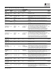
AFD xA 12-Pulse or
Auto Transf High
Temp
Circuit Immediate Latch All
The emergency stop input of the respective AFD was
activated (open circuit has been detected). For RTAE units
with the Input Harmonic Distortion Option installed,
(TDD<5%), the respective drive’s Emergency Stop Fault
input circuitry is used to monitor and trip on the series
connected high limit thermostats of its associated 12-Pulse
Autotransformer. For 200, 230 & 575 V units, the same input
is used to monitor and trip on the series connected high limit
thermostats of the Step-up/Step-down Voltage
Autotransformer. Both circuit diagnostics will occur in the
event of a high temperature trip of the Voltage
Autotransformer. A tripped (open) state of the circuit,
suggests an excessively high temperature of the respective
transformer– Check the glycol cooling loop, the control
panel ventilation or the Voltage Autotransformer panel
ventilation fan as applicable.
Local
AFD xA A/D
Calibration Error
Circuit
Immediate
(decel)
Latch Starting
Before each start, the A/D converters are calibrated against
a known zero-voltage measurement. If the measurement
reads more than 3% of full scale, the AFD asserts this A/D
Calibration Error diagnostic.
Local
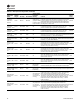
AFD xA AHD
Frequency Out of
Range
Circuit Info NonLatch Running
The input frequency for the Active Harmonic Damping
function of the respective AFD is outside the range 47 Hz <
Fin < 63 Hz for more than one minute. This diagnostic is
automatically reset when the input frequency returns to the
range 47 Hz < Fin < 63 Hz.
Local
AFD xA AHD Sync
Signal Error
Circuit Info NonLatch Running
The Active Harmonic Damping function of the respective
AFD is experiencing noise or glitching of the input line sync
signal continuously for one minute. This diagnostic is
automatically reset when the condition clears.
Local
AFD xA Bump
Failure
Circuit Immediate Latch Bump Mode
During the compressor bump operation, the motor current
exceeded Bump Cutout Current.
Local
AFD xA Bus Over
Voltage
Circuit Immediate NonLatch Holding, Running
Bus overvoltage indicated the high bus voltage cut out has
been exceeded while the AFD is in a non-stopped mode. The
diagnostic will auto-reset when the bus voltage returns to its
normal range for 1 minute.
Local
AFD xA Bus Under
Voltage
Circuit
Immediate
(decel)
NonLatch Holding, Running
The bus voltage dropped below the Low Bus Cutout
threshold and there is not enough voltage to reliably operate
the load. The diagnostic will auto-reset when the bus
voltage returns to its normal range for 1 minute.
Local
AFD xA Bus Voltage
Ripple Too High
Circuit Immediate Latch Running
The DC power bus voltage’s ripple exceeds the drive’s
capability to operate reliably.
Local
AFD xA Comm Loss:
Main Processor
Circuit
Immediate
(decel)
Latch All
The AFD detected a continual loss of communication with
the main processor for greater than the Communications
Loss Time (bound setpoint)
Local
AFD xA Compressor
Start Failure
Circuit Immediate Latch Starting
The compressor motor failed to start. This is most likely due
to load torque (possibly transients) exceeding the torque
capability.
Local
AFD xA Current
Sensor Self Test
Failure
Circuit Immediate Latch Starting
Self testing indicates a current sensor is not working. Either
it output is out of range or it significantly deviates from the
expected current trajectory on self-test
Local
AFD xA
Desaturation
Detected
Circuit Immediate Latch All
Output Short circuit sufficient to drive IGBT transistor gate
into desaturation has been detected
Local
AFD xA DSP Board
ID Error
Circuit
Immediate
(decel)
Latch Power Up
Occurs when frame size identification does not match the
drive software. May occur upon DSP board replacement.
Requires rebinding.
Local
AFD xA DSP Board
Initialization Failure
Circuit
Immediate
(decel)
Latch Power Up
This results from address bus checking, data bus checking,
line sync test, RAM test, each performed during the
initialization
Local
AFD xA DSP Board
Low Voltage Failure
Circuit Immediate NonLatch All
One of the AFD internal power supplies’ voltage has dropped
below a reliable operation threshold
Local
AFD xA DSP Board
Over Temp
Circuit
Immediate
(decel)
NonLatch All
DSP board thermal switch indicates a temperature above
85°C.
Local
Table 32. AFD diagnostics (continued)
Diagnostic
Name and
Source
Affects
Target Severity Persistence
Active Modes
[Inactive
Modes] Criteria
Reset
Level