
Installation and Maintenance Manual


RTAE-SVX001B-EN 73
Diagnostics
Diagnostic Name and Source: Name of Diagnostic and
its source. Note that this is the exact text used in the User
Interface and/or ServiceTool displays.
Affects Target: Defines the “target” or what is affected
by the diagnostic. Usually either the entire Chiller, or a
particular Circuit or Compressor is affected by the
diagnostic (the same one as the source), but in special
cases functions are modified or disabled by the diagnostic.
“None” implies that there is no direct affect to the chiller,
sub components or functional operation.
Design Note: Functions that are affected by a diagnostic
are simply reported as “chiller or circuit x” targets inTracer
TU and on the Alarms page of the AdaptiView™ display,
even though only a specific function and not the entire
circuit or chiller would be effected.
Severity: Defines the severity of the above effect.
Immediate means immediate shutdown of the affected
portion, Normal means normal or friendly shutdown of the
affected portion, Special Action means a special action or
mode of operation (limp along) is invoked, but without
shutdown, and Info means an Informational Note or
Warning is generated. Design Note:TracerTU does not
support display of “Special Action”, on its Diagnostics
pages, so that if a diagnostic has a special action defined
in the table below, it will be displayed only as
“Informational Warning” as long as no circuit or chiller
shutdown results. If there is a shutdown and special action
defined in the table, then theTracerTU Diagnostics Page
display will indicate the shutdown type only.
Persistence: Defines whether or not the diagnostic and
its effects are to be manually reset (Latched), or can be
either manually or automatically reset when and if the
condition returns to normal (Nonlatched).
Active Modes [Inactive Modes]: States the modes or
periods of operation that the diagnostic is active in and, as
necessary, those modes or periods that it is specifically
“not active” in as an exception to the active modes.The
inactive modes are enclosed in brackets, [ ]. Note that the
modes used in this column are internal and not generally
annunciated to any of the formal mode displays.
Criteria: Quantitatively defines the criteria used in
generating the diagnostic and, if nonlatching, the criteria
for auto reset.
Reset Level: Defines the lowest level of manual
diagnostic reset command which can clear the diagnostic.
The manual diagnostic reset levels in order of priority are:
Local or Remote. For example, a diagnostic that has a reset
level of Remote, can be reset by either a remote diagnostic
reset command or by a local diagnostic reset command.
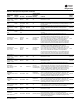
AFD Diagnostics
Table 32. AFD diagnostics
Diagnostic
Name and
Source
Affects
Target Severity Persistence
Active Modes
[Inactive
Modes] Criteria
Reset
Level
AFD xA
Temperature
Sensor Warning
None Info
NonLatch –
timed reset
All
Any of the 3 IGBT modules (one per phase) has an open or
out of range temperature sensor
Local
AFD 1A Voltage
Transient Protection
Loss
None Info NonLatch All
Circuitry for respective AFD “Panel Interlock Warning” was
activated. For RTAE the panel interlock warning input
circuitry of AFD1A, is used to monitor the state of the entire
unit’s Surge Arresters, which is an array of 4 Metal Oxide
Varistors intended to protect the entire unit. An open state
of the circuit suggests at least one of the MOVs has opened
and the transient suppression protection is thereby
compromised. Although the unit is not shutdown from this
warning diagnostic, it is highly recommended to replace the
protection MOVs as soon as practical, in order to protect
from further damage to the drives as a result of incoming
line transients. Even though the diagnostic has an AFD 1A
prefix, it applies to the entire unit
Local