
Installation and Maintenance Manual


Maintenance
70 RTAE-SVX001B-EN
4. Attach a 3/8” or 1/2” hose with a sightglass in the
middle to the oil sump service valve (1/4” flare) and the
oil separator service valve (1/4” flare). See Figure 65,
p. 70 for valve locations.
Note: Using
high pressure rated clear hose with
appropriate fittings can help speed up the
process. Hose must be rated to withstand
system pressures as found on unit nameplate.
5. After the unit is off line for 30 minutes, move the
sightglass
along the side of the oil sump.
6. The nominal oil level from the bottom of the oil
separator
should be as shown in Table 31 and
Figure 66, p. 70. Depending on running conditions and
oil heater dwell time, some deviation from nominal
levels
is expected.
Important: If level is less than 4 inches from the bottom
of the oil separator, contact your localTrane
office.
NOTICE:
Equipment Damage!
Never operate the compressor with the sightglass
service valves opened. Close the valves after checking
the oil level. Operating compressors with service valves
open will result in severe oil loss and equipment
damage.
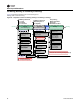
Figure 65. Oil service valves
Table 31. Oil sump level height
Unit Size (tons)
Oil Separator
Size
Nominal Oil
Height
150-200 225 - 300
Oil Separator Size 10” 12”
Nominal Oil Charge Height
in (mm)
9 8.5
To Oil Separator Service Valve
Oil Service Valve
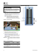
Figure 66. Nominal oil level
To Oil Separator
Service Valve
Nominal oil level
should be:
10” oil sep: 9.0”
12” oil sep: 8.5”