
Installation and Maintenance Manual


Start-Up and Shutdown
RTAE-SVX001B-EN 63
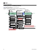
Running (Lead Compressor/Circuit Start and Run)
Figure 58 shows a typical start and run sequence for the
lead compressor and its circuit.
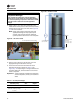
Running (Lag Compressor/Circuit Start and Run)
Figure 59 shows a typical start and run sequence for the
lag compressor and its circuit.
Figure 58. Sequence of operation: running (lead compressor/circuit start nd run)
*Note: The decision to stage on or off another compressor is determined by
the Average Running Compressor Load Command, Water Temperature Error, and Time Since Last Stage
Hold EXV Pre-position
(10 Seconds)
Lead
Compressor
Running
Chiller and Lead Circuit
Mode is “Running” -Lag
Circuit Mode is “Auto”
Hold EXV of Lead
Circuit at pre-
position for 10 sec
De-energize
Oil Heaters
Of Lead Circuit
Control Lead Circuit
Condenser Fans for
Optimum Differential
Pressure,
ƒ(Cprsr Spd, OA Temp)
6
6
6
/
/
/
/
/
1
1
1
2
2
2
/
/
/
/
/
2
2
2
0
0
0
1
1
1
2
2
2
-
1
1
1
2
2
2
/
/
/
/
/
1
1
1
1
1
1
/
/
/
/
/
2
2
2
0
0
0
1
1
1
2
2
2
Enforce All Running Mode Diagnostics for Chiller, Lead Compressor and its Circuit
Modulate EXV for
Liquid Level &
Pressure Control
Modulate
Compressor
Speed for
Limit Control
Modulate Compressor
Speed for
Capacity Control
Modulate Compressor
Speed for
Capacity Control
6
6
6
/
/
/
1
1
1
2
2
2
/
/
/
2
2
2
0
0
0
1
1
1
2
2
2
-
7
7
/
/
/
2
2
2
4
4
4
/
/
/
2
2
2
0
0
0
1
1
1
2
2
2
Running
6
/
1
3
/
/
2
0
1
2
7
7
/
/
/
/
/
/
2
2
2
2
2
2
3
3
3
/
/
/
2
2
2
0
0
0
1
1
1
2
2
2
-
8
8
8
/
/
/
1
1
1
4
4
4
/
/
/
2
2
2
0
0
0
0
0
1
1
2
2
Running
7
/
2
4
/
/
2
0
1
2
8
/
1
4
/
2
0
1
2
-
9
/
1
1
/
2
0
1
2
Running
Lead Circuit:
Running Limit
8
/
1
5
/
/
2
0
1
2
6
/
/
1
1
1
1
3
3
/
/
2
2
2
2
2
0
0
0
0
0
0
1
1
1
1
2
2
2
2
M
i
l
e
s
t
o
n
n
n
n
e
e
D
D
e
e
e
e
e
s
s
c
c
r
r
i
i
i
p
p
t
t
t
i
i
i
o
o
n
n
9
9
9
/
/
/
1
1
1
0
0
0
/
/
/
2
2
2
0
0
0
1
1
1
2
2
2
-
1
1
1
0
0
0
/
/
/
2
2
2
9
9
9
/
/
/
2
2
2
0
0
0
1
1
1
2
2
2
Running
9
r
/
/
/
1
1
/
/
2
0
1
2
Exit
Limit Mode
Enter
Limit Mode
Stage On
Setpoint Met*
0
/
2
8
/
2
0
1
2
-
1
2
/
1
1
/
2
0
1
2
Running
Lag Circuit:
Waiting to Start
1
1
1
r
0
0
0
/
2
9
/
2
0
1
2
Prepare to Start
Lag Compressor,
Check for Oil,
Check for LPC
EXV moving to preposition
0to25Seconds
Start Control of
Condenser Fan Flow
on Lag Circuit
Send Start Command
to Lag Compressor
Continue
Running
Pre-Position EXV of
Lag Circuit
1
2
/
1
1
/
/
2
0
1
2
Figure 59. Sequence of operation: running (lag compressor/circuit start nd run)
*Note: The decision to stage on or off another compressor is determined by
the Average Running Compressor Load Command, Water Temperature Error, and Time Since Last Stage
Hold EXV Pre-position
(10 Seconds)
Both
Compressors
Running
Chiller and Both Circuit
Modes are “Running”
Hold EXV of Lag
Circuit at pre-
position for 10 sec
De-energize
Oil Heaters
Of Lag Circuit
Control Both Circuit
Condenser Fans for
Optimum Differential
Pressure,
ƒ(Cprsr Spd, OA Temp)
6
6
6
/
/
/
/
/
1
1
1
2
2
2
/
/
/
/
/
2
2
2
0
0
0
1
1
1
2
2
2
-
1
1
1
2
2
2
/
/
/
/
/
1
1
1
1
1
1
/
/
/
/
/
2
2
2
0
0
0
1
1
1
2
2
2
Enforce All Running Mode Diagnostics for Chiller, Lead Compressor and its Circuit
Modulate EXV for
Liquid Level &
Pressure Control
Modulate
Compressor
Speed for
Limit Control
Modulate Compressor
Speed for
Capacity Control
Modulate Compressor
Speed for
Capacity Control
6
6
6
/
/
/
1
1
1
2
2
2
/
/
/
2
2
2
0
0
0
1
1
1
2
2
2
-
7
7
/
/
/
2
2
2
4
4
4
/
/
/
2
2
2
0
0
0
1
1
1
2
2
2
Running
6
/
1
3
/
/
2
0
1
2
7
7
/
/
/
/
/
/
2
2
2
2
2
2
3
3
3
/
/
/
2
2
2
0
0
0
1
1
1
2
2
2
-
8
8
8
/
/
/
1
1
1
4
4
4
/
/
/
2
2
2
0
0
0
0
0
1
1
2
2
Running
7
/
2
4
/
/
2
0
1
2
6
/
/
1
1
1
1
3
3
/
/
2
2
2
2
2
2
0
0
0
0
0
0
1
1
1
1
2
2
2
2
M
i
l
e
s
t
o
n
n
n
n
e
e
D
D
e
e
e
e
e
s
s
c
c
r
r
i
i
i
p
p
t
t
i
i
i
o
o
n
n
Exit
Limit Mode
Enter
Limit Mode
0
0
/
/
/
2
2
8
8
/
/
/
2
2
0
0
1
1
2
2
-
1
1
2
2
/
/
/
1
1
1
1
/
/
/
2
2
0
0
1
1
2
2
Running
Energize Maximum
Capacity Relay after the
Adjustable Filter Time
(0 to 600 Seconds)
Continue
Running
(Both
Comprsrs
&Max
Capacity
Maximum Capacity
Submode
9
9
9
/
/
/
1
1
1
1
1
1
/
/
/
2
2
2
0
0
0
1
1
1
2
2
2
-
1
1
1
0
0
0
/
/
/
3
3
3
0
0
0
/
/
/
2
2
2
0
0
0
1
1
1
2
2
2
Running
8
/
1
3
/
2
0
1
2
-
9
/
1
1
/
2
0
0
1
1
2
Running
Lag Circuit:
Running Limit
9
/
1
1
/
/
2
0
1
2
8
/
1
3
/
/
2
0
1
2
1
1
1
0
0
0
r
/
/
/
3
0
/
/
2
0
1
2
2
2
Both Compressors Running
At or Near Max Speed
(Unable to Achieve CWSP)