
Installation and Maintenance Manual


Start-Up and Shutdown
RTAE-SVX001B-EN 61
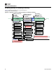
Power Up to Starting
Figure 56, p. 61 diagram shows the timing from a power
up event to energizing the 1
st
compressor.The shortest
allowable time would be under the following conditions:
• No motor restart inhibit time left from subsequent
starts
• Evaporator Water flow occurs quickly with pump on
command
• Power up Start Delay set to 0 minutes
• Need to cool (differential to start) already exists
• Oil level is detected immediately
The above conditions would allow for a minimum power
up to starting the 1
st
compressor time of about 45 seconds
(variations may exist due to options installed). Note that it
is not advisable to start a chiller “cold”, the oil heaters
should be in operation for a sufficient length of time prior
to first start. Consult the chiller’s IOM for specifics.
Figure 56. Sequence of events: power up to starting
6
/
1
2
/
2
0
1
2
-
1
2
/
1
1
/
2
0
1
2
Confirm Presence
of Oil Within
90 Seconds
/
1
1
1
1
5
5
/
/
2
2
2
0
0
0
0
0
C
0
0
1
1
C
2
2
o
Power
Applied
* Lead Compressor (and its lead circuit) is
determined b
y
sta
g
in
g
al
g
orithm –“Fixed Sta
g
in
g
”
6
6
6
6
6
6
/
/
/
/
/
/
/
1
1
1
1
1
1
1
1
2
2
2
2
2
2
2
/
/
/
/
/
/
/
2
2
2
2
2
2
2
0
0
0
0
0
0
0
1
1
1
1
1
1
1
2
2
2
2
2
2
2
-
-
7
7
7
7
7
7
7
/
/
/
/
/
/
/
3
3
3
3
3
3
3
/
/
/
/
/
/
2
2
2
2
0
0
1
1
2
2
Power
Up
6
/
1
3
/
2
0
1
2
UC800
Boot Time
(25 Sec)
Auto Mode commanded
by Front Panel or BAS
EXVs self-
close on
power up
Confirm Evaporator Water Flow
(6 Second Filter)
Enforce Restart Inhibit Timer
(0 to 1 minute)
Power Up Delay Inhibit Timer
(User Adjustable 0 to 30 minutes)
7
7
7
7
7
/
/
/
/
/
2
2
2
2
2
/
/
/
/
/
2
2
2
2
2
0
0
0
0
0
1
1
1
1
1
2
2
2
2
2
-
9
9
9
9
9
/
/
/
/
/
3
3
3
3
3
/
/
/
/
/
2
2
2
2
2
0
0
0
0
0
1
1
1
1
1
2
2
2
2
2
Auto
Energize Evaporator
Water Pump Relay
6
/
1
2
/
2
0
1
2
-
1
2
/
1
1
/
2
0
1
2
Confirm Evaporator Water
Flow Within 20 minutes
(6 Second Filter)
Oil Heaters
Always Energized
when Compressor
is De-energized
6
/
/
1
1
4
4
4
/
2
2
2
0
W
1
W
2
W
a
7
7
/
/
3
3
3
/
/
2
2
2
0
EE
1
2
ff
a
s
s
d
E
E
((
00
f
E
E
n
n
00
EXV remains closed
Wait for Need
To Cool
(Diff to Start)
9
9
9
9
9
9
9
9
/
/
/
/
/
/
/
/
2
2
2
2
2
/
/
/
/
/
2
2
2
2
2
0
0
0
0
0
1
1
1
1
1
2
2
2
2
2
-
1
1
1
1
1
0
0
0
0
0
/
/
/
/
/
2
2
2
2
2
/
/
/
/
/
2
2
2
2
2
0
0
0
0
0
1
1
1
1
1
2
2
2
2
2
Auto
9
/
3
/
2
2
2
0
0
0
0
1
1
(
(
2
2
a
s
s
d
f
Call for Cooling
(Differential to Start is met)
1
1
1
1
1
1
1
1
0
0
0
0
0
2
2
0
0
0
/
/
/
/
/
/
1
1
1
1
1
1
/
/
/
/
/
/
2
2
2
2
2
2
0
0
0
0
0
0
1
1
1
1
1
1
2
2
2
2
2
2
-
-
1
1
1
1
1
1
0
0
0
0
0
0
/
/
/
/
/
/
3
3
3
3
3
3
1
1
1
1
1
1
/
/
/
/
/
/
2
2
2
2
2
2
0
0
0
0
0
0
1
1
1
2
2
Waiting
To Start
0
/
2
/
2
0
1
2
a
s
d
f
Confirm
Presence of Oil
(0 to 90 seconds)
1
1
1
1
1
1
0
0
0
0
0
0
/
/
/
/
/
/
3
3
3
3
3
3
0
0
0
0
0
0
/
/
/
/
/
/
2
2
2
2
2
2
0
0
0
0
0
0
1
1
1
1
1
1
2
2
2
2
2
2
-
-
1
1
1
1
1
1
2
2
2
2
2
2
/
/
/
/
/
/
1
1
1
1
1
1
1
1
1
1
1
1
/
/
/
/
/
/
2
2
2
2
2
2
0
0
0
0
0
0
1
1
1
1
1
1
2
2
2
2
2
2
Waiting
To Start
0
/
3
1
/
2
0
1
2
a
s
d
f
1
2
/
1
1
/
2
0
1
2
a
s
d
f
EXV moving to
Preposition
0 to 25 Seconds
Send Start Command
to Lead Compressor*
Transition to
Running
Start Control of
Condenser Fan Flow
Pre-Position EXV of
Lead Circuit
6
6
6
6
6
6
/
/
/
/
/
/
1
1
1
1
1
1
3
3
3
3
3
3
/
/
/
/
/
/
2
2
2
2
2
2
0
0
0
0
0
0
1
1
1
1
1
1
2
2
2
2
2
2
-
-
-
1
1
1
1
1
1
2
2
2
2
2
2
/
/
/
/
/
/
1
1
1
1
1
1
0
0
0
0
0
0
/
/
/
/
/
/
2
2
2
2
2
2
0
0
0
0
0
0
1
1
1
1
1
1
2
2
2
2
2
2
Check Evap Pressure for
Low Pressure Cutout
6
/
1
1
1
4
4
/
/
2
P
0
P
r
1
e
2
P
L
* Lead compressor (and its lead circuit) is
determined by staging algorithm - “Fixed Staging”
or “Balanced Wear” selection - also influenced by
lockouts, restart inhibit, or diagnostics present.