
Installation and Maintenance Manual


Controls
RTAE-SVX001B-EN 49
Equipment Settings
You can use the TD7 display to monitor and change a
variety of equipment settings.
Viewing the Settings Screen
Touch the Settings button in the main menu area (see
Figure 30, p. 44) to view the Settings screen. Equipment
Settings identifies a column of buttons located on the
screen (see the outlined column in Figure 39).The buttons
are:
• Chiller Settings
• Feature Settings
• Chiller Water Reset
• Manual Control Settings
Each of these buttons provide access to a screen that
contains
additional buttons related to each topic. This
section provides detailed information about these
screens.
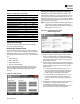
Viewing and Changing Equipment Settings
Each button in the Equipment Settings column on the
Settings screen takes you to a menu screen that contains
a group of buttons. Each button displays the name of a
setting and its current value (Figure 40).Touch any button
to view a screen where you can change the setting for the
feature shown on the button.
Note: A page number appears in the lower right corner of
the screen. If a screen contains more than one
page, up/down arrows also appear for viewing the
other pages, as in Figure 40.
To change an equipment setting, follow this procedure:
1. Touch one of the button in the Equipment Settings
column on the Settings screen, such as Chiller Settings.
The corresponding screen appears (in this case, the
Chiller Settings screen).
2. Touch the button that shows the equipment setting you
w
ant to change. A screen that allows you to change the
equipment setting appears.There are two types of
these screens:
a. For screens with button selections (Figure
41),
touch the button that represents the setting you
want.The button becomes shaded, and a Save
button appears at the bottom of the screen.
b. For screens with numerical keypads (Figure 42),
touch the appropriate numbers to change the
current value.The new value appears above the
keypad.
3. Touch Save to complete the change.The current value
is
updated in the upper left side of the screen,
demonstrating that the change has been
communicated to theTracer UC800 controller.The
screen you were previously viewing appears.
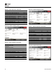
Table 28. Report motor screen items
Description Resolution Units
Active Current Limit Setpoint X.X %RLA
Average Motor Current %RLA X.X %RLA
Starter Motor Current L1 %RLA X.X %RLA
Starter Motor Current L2 %RLA X.X %RLA
Starter Motor Current L3 %RLA X.X %RLA
Starter Motor Current L1 X.X A
Starter Motor Current L1 X.X A
Starter Motor Current L1 X.X A
Starter Input Voltage AB XXX.X V
Starter Input Voltage BC XXX.X V
Starter Input Voltage CA XXX.X V
Average Motor Current X.X A
Average Phase Voltage XXX.X V
Frequency Command XX.X Hz
Figure 39. Setting screen
Figure 40. Equipment setting screen
(Chiller setting shown)