
Installation and Maintenance Manual


Controls
RTAE-SVX001B-EN 43
Communication Interfaces
There are four connections on the UC800 that support the
communication interfaces listed. See Figure 27, p. 42 for
the locations of each of these ports.
• BACnet
®
MS/TP
• MODBUS™ Slave
• LonTalk™ using LCI-C (from the IPC3 bus)
• Comm 4 usingTCI (from the IPC3 bus)
Rotary Switches
There are three rotary switches on the front of the UC800
controller. Use these switches to define a three-digit
address when the UC800 is installed in a BACnet or
MODBUS system (e.g., 107, 127, etc.).
Note: Valid addresses are 001 to 127 for BACnet and 001
to 247 for MODBUS.
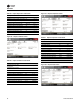
LED Description and Operation
There are 10 LEDs on the front of the UC800. Figure 28
shows the locations of each LED and Table 22 describes
their behavior in specific instances.
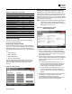
Tracer AdaptiView TD7 Display
Operator Interface
Information is tailored to operators, service technicians,
and owners. When operating a chiller, there is specific
information you need on a day-to-day basis—setpoints,
limits, diagnostic information, and reports. Day-to-day
operational information is presented at the display.
Logically organized groups of information— chiller modes
of operation, active diagnostics, settings and reports put
information conveniently at your fingertips.
Figure 28. LED locations
LINK
LINK MBUS IMC
TX
RX
ACT
SERVICE
Marquee
Table 22. LED behavior
LED UC800 Status
Marquee LED
Powered. If the Marquee LED is green solid, the
UC800 is powered and no problems exist.
Low power or malfunction. If the Marquee LED is
red solid, the UC800 is powered, but there are
problems present.
Alarm. The Marquee LED blinks Red when an alarm
exists.
LINK, MBUS,
IMC
The TX LED blinks green at the data transfer rate
when the UC800 transfers data to other devices on
the link.
The Rx LED blinks yellow at the data transfer rate
when the UC800 receives data from other devices on
the link.
Ethernet Link
The LINK LED is solid green if the Ethernet link is
connected and communicating.
The ACT LED blinks yellow at the data transfer rate
when data flow is active on the link.
Service
The Service LED is solid green when pressed. For
qualified service technicians only. Do not use.
NOTICE:
Electrical Noise!
Maintain at least 6 inches between low-voltage (<30V)
and high voltage circuits. Failure to do so could result i
electrical noise that could distort the signals carried by
the low-voltage wiring, including IPC.
Figure 29. TD7 screens
Operator Display Boot Screen Display Loading Data Home Screen, Auto Mode