
Installation and Maintenance Manual


Installation Electrical
38 RTAE-SVX001B-EN
Tracer (Comm 3).The arbitration of the various sources of
demand limit is described in the flow charts at the end of
this section.The External Demand Limit Setpoint may be
changed from a remote location by hooking up the analog
input signal to the 1K14 LLID terminals 2 and 3. Refer to the
following paragraph on Analog Input Signal Wiring
Details.The following equations apply for EDLS:
If the EDLS input develops an open or short, the LLID will
report either a very high or very low value back to the man
processor.This will generate an informational diagnostic
and the unit will default to using the Front Panel (Tracer
AdaptiView™TD7) Current Limit Setpoint.
TheTracer™TU ServiceTool must be used to set the input
signal type from the factory default of 2-10 VDC to that of
4-20 mA current.TracerTU must also be used to install or
remove the External Demand Limit Setpoint Option for
field installation, or can be used to enable or disable the
feature (if installed).
EDLS and ECWS Analog Input Signal Wiring
Details:
Both the ECWS and EDLS can be connected and setup as
either a 2-10 VDC (factory default), 4-20 mA, or resistance
input (also a form of 4-2OmA) as indicated below.
Depending on the type to be used, theTracerTU Service
Tool must be used to configure the LLID and the MP for the
proper input type that is being used.This is accomplished
by a setting change on the Custom Tab of the
Configuration View withinTracerTU.
Important: For proper unit operation, BOTH the EDLS
and ECWS settings MUST be the same (2-10
VDC or 4-20mA), even if only one input is to
be used.
The J2-3 and J2-6 terminal is chassis grounded and
terminal J2- 1 and J2-4 can be used to source 12 VDC.The
ECLS uses terminals J2-2 and J2-3. ECWS uses terminals
J2-5 and J2-6. Both inputs are only compatible with
high-side current sources.
Chilled Water Reset (CWR)
UC800 resets the chilled water temperature set point
based on either return water temperature, or outdoor air
temperature. Return Reset is standard, Outdoor Reset is
optional.
The following shall be selectable:
• One of three ResetTypes: None, Return Water
Temperature Reset, Outdoor AirTemperature Reset, or
Constant Return WaterTemperature Reset.
• Reset Ratio Set Points.
For outdoor air temperature reset there shall be both
positive and negative reset ratio's.
• Start Reset Set Points.
• Maximum Reset Set Points.
The equations for each type of reset are as follows:
Return
CWS' = CWS + RATIO (START RESET - (TWE -TWL))
and CWS' > or = CWS
and CWS' - CWS < or = Maximum Reset
Outdoor
CWS' = CWS + RATIO * (START RESET -TOD)
and CWS' > or = CWS
and CWS' - CWS < or = Maximum Reset
where
CWS' is the new chilled water set point or the "reset CWS"
CWS is the active chilled water set point before any reset
has occurred, e.g. normally Front Panel,Tracer, or ECWS
RESET RATIO is a user adjustable gain
START RESET is a user adjustable reference
TOD is the outdoor temperature
TWE is entering evap. water temperature
Voltage Signal Current Signal
As generated from
external source
VDC+0.133*(%)-6.0 mA=0.266*(%)-12.0
As processed by
UCM
%=7.5*(VDC)+45.0 %=3.75*(mA)+45.0
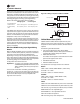
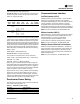
Figure 25. Wiring examples for EDLS and ECWS
J2-1 & 4 Dual
J2-2 & 5 Analog
J2-3 & 6 I/O LLID
J2-1 & 4 Dual
J2-2 & 5 Analog
J2-3 & 6 I/O LLID
J2-1 & 4 Dual
J2-2 & 5 Analog
J2-3 & 6 I/O LLID
Resister
2-10 VDC, 4-20mA
I = 20/(R + 200)
I