
Installation and Maintenance Manual


Installation Electrical
36 RTAE-SVX001B-EN
Relay Assignments Using
Tracer™ TU
Tracer™TU ServiceTool is used to install the
Programmable Relay Option package and assign any of
the above list of events or status to each of the four relays
provided with the option. (See “Tracer™TU,” p. 55 for
more information on theTracerTU service tool.) The
relays to be programmed are referred to by the relay’s
terminal numbers on the LLID board 1K13.
The default assignments for the four available relays of the
Programmable Relay option are:
If any of the Alarm/Status relays are used, provide
electrical power, 115 VAC with fused-disconnect to the
panel and wire through the appropriate relays (terminals
on 1K13 (EUR=A4-5)). Provide wiring (switched hot,
neutral, and ground connections) to the remote
annunciation devices. Do not use power from the chiller’s
control panel transformer to power these remote devices.
Refer to the field diagrams which are shipped with the unit.
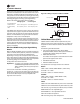
Low Voltage Wiring
The remote devices described below require low voltage
wiring. All wiring to and from these remote input devices
to the Control Panel must be made with shielded, twisted
pair conductors. Be sure to ground the shielding only at
the panel.
Important: To prevent control malfunctions, do not run
low voltage wiring (<30 V) in conduit with
conductors carrying more than 30 volts.
Emergency Stop
UC800 provides auxiliary control for a customer specified/
installed latching trip out. When this customer-furnished
remote contact 5K35 is provided, the chiller will run
normally when the contact is closed. When the contact
opens, the unit will trip on a manually resettable
diagnostic.This condition requires manual reset at the
front of the control panel.
Connect low voltage leads to terminal strip locations on
1K2. Refer to the field diagrams that are shipped with the
unit.
Silver or gold-plated contacts are recommended.These
customer-furnished contacts must be compatible with 24
VDC, 12 mA resistive load.
External Auto/Stop
If the unit requires the external Auto/Stop function, the
installer must provide leads from the remote contacts
5K34 to the proper terminals of the LLID 1K2 on the control
panel.
The chiller will run normally when the contacts are closed.
When either contact opens, the compressor(s), if
operating, will go to the RUN:UNLOAD operating mode
and cycle off. Unit operation will be inhibited. Closure of
the contacts will permit the unit to return to normal
operation.
Field-supplied contacts for all low voltage connections
must be compatible with dry circuit 24 VDC for a 12 mA
resistive load. Refer to the field diagrams that are shipped
with the unit.
External Circuit Lockout – Circuit #1 and #2
UC800 provides auxiliary control of a customer specified
or installed contact closure, for individual operation of
either Circuit #1 or #2. If the contact is closed, the
refrigerant circuit will not operate 5K32 and 5K33.
Alarm Ckt 1
This output is true whenever there is any
active latching or non-latching shutdown
diagnostic that targets Circuit 1, or any of the
Compressors on Circuit
Alarm Ckt 2
This output is true whenever there is any
active latching or non-latching shutdown
diagnostic that targets Circuit 2, or any of the
Compressors on Circuit 2.
Unit Limit Mode
This output is true whenever a circuit on the
unit has been running in one of the limit
modes continuously for the Limit Relay
debounce time. A given limit or overlapping of
different limits must be in effect continuously
for the debounce time prior to the output
becoming true. It will become false if no limits
are present for the debounce time.
Compressor Running
The output is true whenever any compressor
is running.
Circuit 1 Running
The output is true whenever any compressor
of Circuit 1 is running.
Circuit 2 Running
The output is true whenever any compressor
of Circuit 2 is running.
Maximum Capacity
The output is true whenever the unit has
reached maximum capacity continuously for
the Max Capacity Relay debounce time. The
output is false when the unit is not at
maximum capacity continuously for the filter
debounce time.
Head Pressure Relief
Request
This relay output is energized anytime the
chiller or a single circuit on the chiller is
running in one of the following modes; Ice
Making Mode, or Condenser Pressure Limit
continuously for the duration specified by the
Chiller Head Relief Relay Filter Time. The
Chiller Head Relief Relay Filter Time is a
service setpoint. The relay output is de-
energized anytime the chiller exits all above
modes continuously for the duration specified
by the same Chiller Head Relief Relay Filter
Time
Table 20. Default assignments
Relay
Relay 0Terminals J2-1,2,3: Unit Limit Mode
Relay 1Terminals J2-4,5,6: Maximum Capacity
Relay 2Terminals J2 - 7,8,9: Compressor Running
Relay 3Terminals J2 -10,11,12: Alarm
Table 19. Alarm and status relay output configuration
table (continued)
Description