
Installation and Maintenance Manual


Installation Electrical
34 RTAE-SVX001B-EN
Cut holes into the location shown above for the
appropriately-sized power wiring conduits. The wiring is
passed through these conduits and connected to the
terminal blocks, optional unit-mounted disconnects, or
HACR type breakers.
The high voltage field-provided connections are made
through patch plate on the right side of the main control
panel or on the right side of the voltage autotransformer
panel.
The low voltage connections are made through knockouts
provided on the left side of the control panel. Additional
grounds may be required for each 115 volt power supply to
the unit. Green lugs are provided for 115V customer
wiring.
Control Power Supply
The unit is equipped with a control power transformer. It
is not necessary to provide additional control power
voltage to the unit. No other loads should be connected to
the control power transformer.
All units are factory-connected for appropriate labeled
voltages.
Service Power Connection
The service power connection is a touch safe procedure to
allow for binding the control system and LLIDs. Service
power connection allows for a NEMA 5-15 style extension
cord to power on Class 2 devices (i.e. UC800, LLIDs, EXVs,
andTD7 display) with an external power source, without
the need of line voltage applied to the unit.This connection
is to be made at 1XJ50.The extension cord power source
is required to have upstream current protection rated at no
more than 10A.The required voltage for the service power
connection is 115V at 60Hz and 110V at 50Hz.
Heater Power Supply
The evaporator shell is insulated from ambient air and
protected from freezing temperatures by thermostatically-
controlled immersion heaters. See Table 17 for evaporator
heater summary. Whenever the water temperature drops
to approximately 37°F (2.8°C), the thermostat energizes
the heaters.The heaters will provide protection from
ambient temperatures down to -20°F (-29°C).
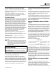
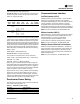
Figure 24. Incoming customer power - transformer
200V, 230V and 575V units
(Includes optional Transformer
model number digit 28 = 1)
Incoming Customer Power Location
On Transformer
End of Unit
(non-control panel end)
Right side of unit
Incoming Customer
Power Location
(located on transformer)
Incoming Customer
Power Location
(located on transformer)
NOTICE:
Equipment Damage!
Control panel main processor does not verify
thermostat operation. A qualified technician must
confirm operation of the thermostat to avoid
catastrophic damage to the evaporator.
Table 17. Evaporator heater summary
Unit Size (tons)
Waterboxes
Supply Return
2-pass Evaporator
150-165 400W 400W
180-200 400W (Qty 2) 400W
225-300 600W 600W
3-pass Evaporator
All sizes 400W (Qty 2) 400W