
Installation and Maintenance Manual


Installation Electrical
RTAE-SVX001B-EN 33
Power Supply Wiring
All power supply wiring must be sized and selected
accordingly by the project engineer in accordance with
NECTable 310-16.
All wiring must comply with local codes and the National
Electrical Code.The installing (or electrical) contractor
must provide and install the system interconnecting
wiring, as well as the power supply wiring. It must be
properly sized and equipped with the appropriate fused
disconnect switches.
The type and installation location(s) of the fused
disconnects must comply with all applicable codes.
Incoming customer power location varies with unit
configurations.
• Control Panel (see Figure 23)
• Standard length units
(model number digits 28, 29 = 0X)
• Units with optional harmonic filtration
(model number digit 29 = 1)
• Transformer (see Figure 24, p. 34)
• 200, 230 or 575 V units with transformer
(model number digit 28 = 1)
WARNING
Proper Field Wiring and Grounding
Required!
All field wiring MUST be performed by qualified
personnel. Improperly installed and grounded field
wiring poses FIRE and ELECTROCUTION hazards.To
avoid these hazards, you MUST follow requirements for
field wiring installation and grounding as described in
NEC and your local/state electrical codes. Failure to
follow code could result in death or serious injury.
WARNING
Hazardous Voltage w/Capacitors!
Disconnect all electric power, including remote
disconnects and discharge all motor start/run
capacitors before servicing. Follow proper lockout/
tagout procedures to ensure the power cannot be
inadvertently energized. For variable frequency drives or
other energy storing components provided by Trane or
others, refer to the appropriate manufacturer’s literature
for allowable waiting periods for discharge of
capacitors. Verify with an appropriate voltmeter that all
capacitors have discharged. Failure to disconnect power
and discharge capacitors before servicing could result in
death or serious injury.
DC bus capacitors retain hazardous voltages after input
power has been disconnected. Follow proper lockout/
tagout procedures to ensure the power cannot be
inadvertently energized. After disconnecting input
power, wait five (5) minutes for the DC capacitors to
discharge and then check the voltage with a voltmeter
to ensure the dc bus capacitors are discharged before
touching any internal components. Failure to observe
this precaution could result in death or serious injury.
For additional information regarding the safe discharge
of capacitors, see “Adaptive Frequency™ Drive (AFD
3
)
Capacitor Discharge,” p. 32 and PROD-SVB06A-EN.
NOTICE:
Use Copper Conductors Only!
Unit terminals are not designed to accept other types
of conductors. Failure to use copper conductors could
result in equipment damage.
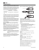
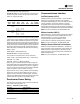
Figure 23. Incoming customer power - control panel
Control Panel
Incoming Customer
Power Location
Standard Length Units
(model number digits 28, 29 = 0X)
Unit with optional Harmonic Filtration
(model number digit 29 = 1)
Incoming
Customer
Power
Location
Pulse Auto Transformer
(harmonic filtration)
Control Panel
Incoming Customer Power Location
Unit Control Panel - right side view
Incoming
Customer
Power
Location