
Installation and Maintenance Manual


Installation Electrical
32 RTAE-SVX001B-EN
Adaptive Frequency™ Drive (AFD
3
)
Capacitor Discharge
After disconnecting input power, wait five (5) minutes for
the DC capacitors to discharge.
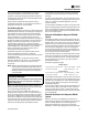
Using voltmeter, measure voltage on bus at bus indicator
module tabs 1 and 2, accessed through slots in protective
cover on drive. See Figure 21, p. 32 for location of bus
indicator module on the AFD drive. See Figure 22, p. 32 for
details of bus indicator module. Capacitors are fully
discharged when voltage across these tabs measures 0
VDC.
Units with Nitrogen Charge Option
For units with nitrogen charge option (model number digit
15 = 2), the unit must NOT have shore power, or unit power
applied until the unit has been charged. Applying power
will drive EXV valves closed, and will inhibit sufficient vac
for unit charging.
Installer-Supplied Components
Customer wiring interface connections are shown in the
electrical schematics and connection diagrams that are
shipped with the unit.The installer must provide the
following components if not ordered with the unit:
• Power supply wiring (in conduit) for all field-wired
connections.
• All control (interconnecting) wiring (in conduit) for
field
supplied devices.
• Fused-disconnect switches or circuit breakers.
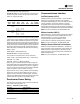
Figure 21. AFD board - indicator location
Figure 22. Bus indicator module detail
Bus
Indicator
Module
Tab 2
(-) Bus
Tab 1
(+) Bus
Bus Charge
Indicator
DC Bus Voltage
Indicator LED
N2