
Installation and Maintenance Manual


Installation Mechanical
26 RTAE-SVX001B-EN
Pressure Relief Valves
Install a water pressure relief valve in the evaporator inlet
piping between the evaporator and the inlet shutoff valve,
as shown in Figure 17, p. 25. Water vessels with close-
coupled shutoff valves have a high potential for
hydrostatic pressure buildup on a water temperature
increase. Refer to applicable codes for relief valve
installation guidelines.
Evaporator Flow Switch
The flow switch is factory-installed and programmed
based on the operating conditions submitted with the
order.The leaving evaporator temperature, fluid type and
fluid concentration affect the selected flow switch. If the
operating conditions on the job site change, the flow
switch may need to be replaced. Contact your localTrane
Sales office for more information.
The sensor head includes 3 LEDs, two yellow and one
green.Wait 15 seconds after power is applied to the sensor
before evaluating LEDs for flow status. When wired
correctly and flow is established, only the green LED
should be lit. Following are the LED indicators:
• Green ON, both yellow OFF — Flow
• Green and outside yellow ON — No Flow
• Center yellow ON continuously — Miswire
Factory installed jumper wire W11 must be removed if
using auxiliary contacts and/or additional proof of flow.
See schematics in RTAE-SVE01*-EN for more details.
If using auxiliary flow sensing, both yellow LEDs come on
initially when flow is stopped.The center yellow LED will
turn off after approximately 7 seconds.The LED indicators
are otherwise the same as indicated above.
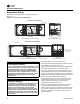
Indexing Flow Switch
To properly index the flow switch, the following
requirements must be met:
• The dot must be at a position no greater than 90° off
Index.
• The torque must be between 22 ft-lb minimum and 74
ft-lb maximum.
• A minimum distance of 5x pipe diameter must be
maintained between flow switch and any bends,
valves, changes in cross sections, etc.
NOTICE:
Evaporator Damage!
To prevent shell damage, install pressure relief valves in
the evaporator water system.
NOTICE:
Equipment Damage!
Flow switch is on a 24V circuit. Do NOT apply 120V to
the flow switch. Incorrect voltage application could
cause damage to the flow switch.
NOTICE:
Equipment Damage!
Incorrect wiring of auxiliary contacts could cause
equipment damage.
Figure 18. Proper flow switch indexing
Flow
Top View
Index
The flow switch must have the dot
in the shaded area to the left of this line
for proper indexing (±90° off Index)