
Installation and Maintenance Manual


Installation Mechanical
RTAE-SVX001B-EN 25
Evaporator Piping Components
Piping components include all devices and controls used
to provide proper water system operation and unit
operating safety. SeeThese components and their general
locations are given below.
Entering Chilled Water Piping
• Air vents (to bleed air from system).
• Water pressure gauges with shutoff valves.
• Vibration eliminators.
• Shutoff (isolation) valves.Thermometers (if desired).
• Clean-out tees.
• Pipe strainer.
Leaving Chilled Water Piping
• Air vents (to bleed air from system).
• Water pressure gauges with shutoff valves.
• Vibration eliminators.
• Shutoff (isolation) valves.
• Thermometers.
• Clean-out tees.
• Balancing valve.
Drains
A 1/2” drain connection is located under outlet end of
evaporator waterbox for drainage during unit servicing. A
shutoff valve must be installed on drain line.
Pressure Gauges
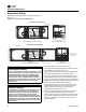
Install field-supplied pressure components as shown in
Figure 17, p. 25. Locate pressure gauges or taps in a
straight run of pipe; avoid placement near elbows, etc. Be
sure to install the gauges at the same elevation on each
shell if the shells have opposite-end water connections.
To read manifolded pressure gauges, open one valve and
close the other (depending upon the reading desired).This
eliminates errors resulting from differently calibrated
gauges installed at unmatched elevations.
Figure 17. Typical Stealth™ water piping
Table 14. Water piping components
Item Description Item Description
1 Bypass Valve Pi Pressure Gauge
2 Isolation Valve FT Water Flow Switch
3 Vibration Eliminator T1 Evap Water Inlet Temp Sensor
4 Evaporator - End View (2-pass) T2 Evap Water Outlet Temp Sensor
5 Evaporator Waterbox (2-pass)
NOTES
6 Vent A Isolate unit for initial water loop cleaning
7 Strainer B Vent must be installed at the high point of the line
8 Drain C Drain must be installed at the low point of the line
A
2
1
2
3
3
7
8
6
4
5
2
2
A
A
B
8
C