
Installation and Maintenance Manual


Installation Mechanical
20 RTAE-SVX001B-EN
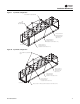
Center of Gravity
Isolation and Sound Emission
The most effective form of isolation is to locate the unit
away from any sound sensitive area. Structurally
transmitted sound can be reduced by elastomeric
vibration eliminators. Spring isolators are not
recommended. Consult an acoustical engineer in critical
sound applications.
For maximum isolation effect, isolate water lines and
electrical conduit.Wall sleeves and rubber isolated piping
hangers can be used to reduce the sound transmitted
through water piping.To reduce the sound transmitted
through electrical conduit, use flexible electrical conduit.
State and local codes on sound emissions should always
be considered. Since the environment in which a sound
source is located affects sound pressure, unit placement
must be carefully evaluated. Sound power levels for
Stealth chillers are available on request.
Unit Isolation and Leveling
For additional reduction of sound and vibration, install the
optional elastomeric isolators.
Construct an isolated concrete pad for the unit or provide
concrete footings at the unit mounting points. Mount the
unit directly to the concrete pads or footings.
Level the unit using the base rail as a reference.The unit
must be level within 1/4-in (6 mm) over the entire length
and width. Use shims as necessary to level the unit.
Elastomeric Isolators
(Optional for units without seismic rating)
Note: See unit submittal, or Table 11, p. 21 thru Table 13,
p. 23 for point weights, isolator location and
isolator selections.
1. Secure the isolators to the mounting surface using the
mounting slots in the isolator base plate. Do not fully
tighten the isolator mounting bolts at this time.
2. Align the mounting holes in the base of the unit with
the threaded positioning pins on the top of the
isolators.
3. Lower the unit onto the isolators and secure the
isolator to the unit with a nut.
4. Level the unit carefully. Fully tighten the isolator
mounting bolts.
Figure 11. Center of gravity
Table 9. Centers of gravity
Tons
CGx CGy CGz
in mm in mm in mm
Standard Length Unit
150S 96.6 2454 43.8 1112 40.4 1025
165S 110.0 2793 45.2 1149 42.8 1087
150 105.5 2679 43.9 1115 37.5 953
165 142.4 3617 43.9 1115 39.7 1008
180 142.8 3628 43.9 1115 39.4 1002
200 155.5 3951 43.9 1115 41.2 1047
225 156.1 3964 43.9 1115 39.8 1011
250 156.4 3973 43.9 1115 39.7 1008
275 194.1 4930 43.9 1115 41.1 1043
300 207.1 5260 43.9 1115 42.4 1076
Extended Length Unit
(a)
(a) Units are extended length if either of the following are selected:
Low Harmonic Distortion Option (model number digit 29 = 1)
Autotransformer (model number digit 28 = 1 or 2)
Units without Low Harmonic Distortion Option or Autotransformer (digits
28, 29 = X0) are standard length.
150S 118.8 3017 44.1 1121 37.2 944
165S 136.4 3464 44.7 1137 39.4 1002
150 134.7 3421 43.9 1115 33.3 846
165 169.1 4295 43.9 1115 35.4 898
180 169.9 4314 43.9 1115 35.2 894
200 181.6 4613 43.9 1115 36.9 937
225 183.6 4665 43.9 1115 36.0 915
250 184.2 4680 43.9 1115 36.0 913
275 220.2 5594 43.9 1115 37.4 950
300 232.3 5900 43.9 1115 38.7 984
SIDE VIEW
X
END VIEW
(Non-Control Panel End)
Z
Y
CG
CG