
Installation and Maintenance Manual


RTAE-SVX001B-EN 15
Installation Mechanical
Location Requirements
Sound Considerations
• Refer toTrane Engineering Bulletin Chiller Sound
Ratings and Installation Guide RLC-PRB035-EN for
sound consideration applications.
• Locate the unit away from sound-sensitive areas.
• Install the optional elastomeric isolators under the
unit. See
“Isolation and Sound Emission,” p. 20.
• Chilled water piping should not be supported by chiller
frame.
• Install rubber vibration isolators in all water piping.
• Use flexible electrical conduit.
• Seal all wall penetrations.
Note: Consult an acoustical engineer for critical
applications.
Foundation
Provide rigid, non-warping mounting pads or a concrete
foundation of sufficient strength and mass to support the
applicable operating weight (i.e., including completed
piping, and full operating charges of refrigerant, oil and
water). See Table 5, p. 14 for unit operating weights. Once
in place, the unit must be level within 1/4” (6.4 mm) across
the length and width of the unit.TheTrane Company is not
responsible for equipment problems resulting from an
improperly designed or constructed foundation.
Clearances
Provide enough space around the unit to allow the
installation and maintenance personnel unrestricted
access to all service points. See submittal drawings for the
unit dimensions, to provide sufficient clearance for the
opening of control panel doors and unit service. See
Figure 5, p. 14 for minimum clearances. In all cases, local
codes which require additional clearances will take
precedence over these recommendations.
For close spacing information, see RLC-PRB037-EN.
Rigging
Important:
• Do not fork lift unit.
• See unit nameplate and/or unit submittal for total
shipping weight.
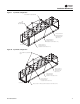
• See Table 6 and Figure 8 thru Figure 10 for unit lifting
configuration.
• See Table 7, p. 18 and Table 8, p. 19 for lift weights and
dimensions at each lifting point locations.
• See Table 9, p. 20 for center of gravity information.
WARNING
Improper Unit Lift!
Test lift unit approximately 24 inches to verify proper
center of gravity lift point. To avoid dropping of unit,
reposition lifting point if unit is not level. Failure to
properly lift unit could result in unit dropping and
possibly crushing operator/technician which could
result in death or serious injury and possible
equipment or property-only damage.
WARNING
Heavy Objects!
Ensure that all the lifting equipment used is properly
rated for the weight of the unit being lifted. Each of the
cables (chains or slings), hooks, and shackles used to
lift the unit must be capable of supporting the entire
weight of the unit. Lifting cables (chains or slings) may
not be of the same length. Adjust as necessary for even
unit lift. Other lifting arrangements could cause
equipment or property damage. Failure to follow
instructions above or properly lift unit could result in
unit dropping and possibly crushing operator/
technician which could result in death or serious injury.
WARNING
Proper Lifting Configuration Required!
Use only lift locations designated with label shown in
Figure 6. Do NOT use locations marked with label
shown in Figure 7. Use unit lifting configurations as
shown in Table 6 and Figure 8, p. 16 thru Figure 10,
p. 17. Other lifting arrangements could result in death,
serious injury or equipment damage.
Figure 6. Label - lift location
Figure 7. Label - do not lift
X39003897001A
X39003894001A