
user manual

Chapter 7 Programming
114 BAS-APG001-EN
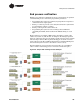
information. A program fragment illustrating the collection process is
shown in
Figure 65.
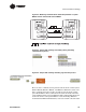
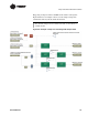
Figure 65. Collection of Tracer and EX2 communication status at an
individual MP581
Figure 65 also shows that each MP581 in the smoke control system
should send back its won watchdog signal to the main FSCP control
MP581.
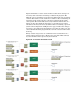
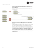
At the main FSCP control MP581, all the communication status signals
are collected together to determine overall communication status.
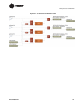
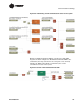
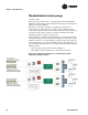
Figure 66 on page 115 shows a TGP sample of the programming. Each
MP581 in the smoke control system sends its own watchdog signal, its
Tracer Summit communication status, and its EX-2 module
communication status. In addition, the main FSCP control MP581 will
have its own Tracer Summit communication status and EX-2 module
communication to determine and add to the calculation. The Comm Fault
LED should indicate if any communication link in the system is not
working correctly.