
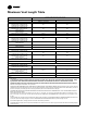
Specifications

22-1930-1C-EN
19
O
Y2
Y1 Y1
B/C B/C
W2W2
W1W1
GG
RR
O
Y1
Two Stage
Thermostat
Furnace
Outdoor Unit
(No Transformer)
SEE
NOTE 1
O
R
X2
Y2
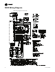
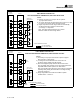
NOTES:
1) Remove the factory Y1-O jumper for HP systems
for proper LED read out.
2) Y1 and Y2 wiring from the thermostat must connect to Y1 and
Y2 of the IFC for proper airflow and LED readout.
3) Single compressor and two stage airflow is automatically
set with the IFC Menu options in ODU section.
2-1=2 stage / 1 compressor
Note: First stage airflow should be set to deliver
between 70-80% of second stage airflow
INTER-COMPONENT WIR
ING
24 V FIELD WIRING
24 V FACTORY WIRING
FIELD WIRING DIAGRAM FOR
TWO STAGE HEATING THERMOSTAT, TWO STAGE HEAT PUMP
Y2
B/C
O
Y2
Y1 Y1
B/C B/C
W2
W1W1
GG
RR
O
Y1
B/C
Single Stage
Thermostat
Furnace
Outdoor Unit
(No Transformer)
SEE
NOTE 1
SEE
NOTE 3
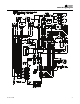
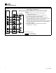
FIELD WIRING DIAGRAM FOR
SINGLE STAGE HEATING THERMOSTAT, SINGLE STAGE COOLING
NOTES:
1) The factory Y1-O jumper must remain in place for proper
LED read out in cooling mode.
2) Y1 wiring from the thermostat must connect to Y1 of
the IFC for proper airflow and LED readout.
3) Place field supplied jumper between W1 and W2 on the
IFC. Interstage delay is factory set for 10 minutes but is field
adjustable with the Menu option in the ISD section.
Note: HT2 will be shown during the entire heating cycle but the
interstage delay setting will control when 2nd stage heating
is actually energized.
4) Single stage airflow is set with the IFC Menu options
in ODU section. Select 1-1.
INTER-COMPONENT WIRING
24 V FIELD WIRING
24 V FACTORY WIRING
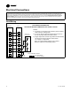
EElleeccttrriiccaall CCoonnnneeccttiioonnss