Product Data Upflow/ Horizontal Left/Right, Downflow Two Stage Condensing Gas Fired Furnace Upflow, Convertible to Horizontal Right or Horizontal Left S9X2B040U2PSAA S9X2B040U3PSAA S9X2B060U3PSAA S9X2B060U4PSAA S9X2B080U3PSAA S9X2B080U4PSAA S9X2C080U4PSAA S9X2C080U5PSAA S9X2C100U4PSAA S9X2C100U5PSAA S9X2D120U5PSAA Downflow Only S9X2B040D2PSAA S9X2B060D3PSAA S9X2B080D4PSAA S9X2C100D5PSAA S9X2D120D5PSAA N o t e : Graphics in this document are for representation only. Actual model may differ in appearance.
General Features NATURAL GAS MODELS Central Heating furnace designs are certified by the American Gas Association for both natural and L.P. gas. Limit setting and rating data were established and approved under standard rating conditions using American National Standards Institute standards. SAFE OPERATION The Integrated System Control is a solid state device which continuously monitors for presence of flame when the system is in the heating mode of operation.
Features and Benefits UP TO 96.
Features and Benefits Easier to specify Shipped ready to install (no conversion kits required) Every model has at least two venting options When in horizontal, trap extends only about 2” Barbed fitting on trap at hose connection and on cabinet transition for hose has barbed fitting and clamps at both ends for leak resistance.
Accessories Table 1.
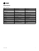
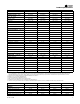
Product Specifications S9X2B040U2PSAA (a) S9X2B040U3PSAA (a) S9X2B060U3PSAA (a) S9X2B060U4PSAA (a) MODEL Upflow/Horizontal Upflow/Horizontal Upflow/Horizontal Upflow/Horizontal 1st Stage Input BTUH (ICS) 26,000 26,000 39,000 39,000 1st Stage Capacity BTUH 25,220 25,220 37,830 37,830 40,000 40,000 60,000 60,000 TYPE RATINGS (b) 2nd Stage Input BTUH 2nd Stage Capacity BTUH (ICS) 38,800 38,800 58,200 58,200 1st Stage Temp. Rise (Min.-Max.
Product Specifications S9X2B040U2PSAA (a) S9X2B040U3PSAA (a) S9X2B060U3PSAA (a) S9X2B060U4PSAA (a) MODEL Max. Overcurrent Protection (Amps) 15 15 15 15 PIPE CONN. SIZE (in.) 1/2 1/2 1/2 1/2 DIMENSIONS HxWxD HxWxD HxWxD HxWxD Uncrated (In.) 34 x 17-1/2 x 28–3/4 34 x 17-1/2 x 28–3/4 34 x 17-1/2 x 28–3/4 34 x 17-1/2 x 28–3/4 Crated (In.) 35-1/2 x 19-1/2 x 30-7/8 35-1/2 x 19-1/2 x 30-7/8 35-1/2 x 19-1/2 x 30-7/8 35-1/2 x 19-1/2 x 30-7/8 WEIGHT Shipping (Lbs.)/Net (Lbs.
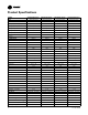
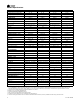
Product Specifications S9X2B080U3PSAA(a) S9X2B080U4PSAA (a) S9X2C080U4PSAA (a) S9X2C080U5PSAA (a) MODEL — Unfired Gauge (Fired) 29–4C Stainless Steel 29–4C Stainless Steel 29–4C Stainless Steel 29–4C Stainless Steel 20 20 20 20 4 - 45 4 - 45 4 - 45 4 - 45 ORIFICES — Main Nat. Gas Qty. — Drill Size LP Gas Qty.
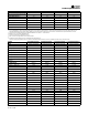
Product Specifications S9X2C100U4PSAA (a) S9X2C100U5PSAA(a) S9X2D120U5PSAA (a) S9X2B040D2PSAA (a) MODEL FLA COMBUSTION FAN — Type Drive — No. Speeds 10.9 10.9 10.9 4.8 Centrifugal Centrifugal Centrifugal Centrifugal Direct - 2 Direct - 2 Direct - 2 Direct - 2 Motor HP — RPM 3300/2600 3300/2600 3300/2600 3300/2600 Volts/Ph/Hz 120 / 1 / 60 120 / 1 / 60 120 / 1 / 60 120 / 1 / 60 0.66 0.66 0.66 0.
Product Specifications MODEL S9X2B060D3PSAA (a) S9X2B080D4PSAA (a) S9X2C100D5PSAA (a) S9X2D120D5PSAA(a) 1st Stage Temp. Rise (Min.-Max.) 25 - 55 30 - 60 30 - 60 30-60 2nd Stage Temp. Rise (Min.-Max.) 35 - 65 35 - 65 35 - 65 40-70 95.0 95.0 95.0 95.0 DIRECT DIRECT DIRECT DIRECT 11 X 8 11 X 8 11 X 10 11 X 10 1 1 1 1 AFUE (%) BLOWER DRIVE Diameter — Width (In.) No. Used Speeds (No.) (e) CFM vs. in. w.g. Motor HP RPM Volts/Ph/Hz FLA COMBUSTION FAN — Type Drive — No.
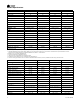
Heating and Cooling Airflow Tables Table 2. Upflow Cooling Table FURNACE AIRFLOW (CFM) VS. STATIC PRESSURE (ins.w.g) MODEL S9X2B040U2PSAA S9X2B040U3PSAA S9X2B060U3PSAA S9X2B060U4PSAA S9X2B080U3PSAA S9X2B080U4PSAA S9X2C080U4PSAA 22-1930-1C-EN SPEED TAP 0.1 0.2 0.3 0.4 0.5 0.6 0.7 0.8 0.
Heating and Cooling Airflow Tables Table 2.
Heating and Cooling Airflow Tables Table 3.
Heating and Cooling Airflow Tables Table 6. 1st Stage Heating Table — Upflow CFM VS.
Maximum Vent Length Table Maximum Total Equivalent Length In Feet for Vent and Inlet Air (See Notes) Maximum Vent Length Table Model 2 Inch or 2.
S9X2 Wiring Diagram S9X2 Wiring Diagram and Schematic 16 22-1930-1C-EN
S9X2 Wiring Diagram 22-1930-1C-EN 17
Electrical Connections Make wiring connections to the unit as indicated on enclosed wiring diagram. As with all gas appliances using electrical power, this furnace shall be connected into a permanently live electric circuit. It is recommended that furnace be provided with a separate "circuit protection device" electric circuit. The furnace must be electrically grounded in accordance with local codes or in the absence of local codes with the National Electrical Code, ANSI/NFPA 70 or CSA C22.
Electrical Connections Two Stage Thermostat Furnace FIELD WIRING DIAGRAM FOR TWO STAGE HEATING THERMOSTAT, TWO STAGE HEAT PUMP Outdoor Unit (No Transformer) W2 W2 W1 W1 X2 R R R G G B/C B/C Y2 Y2 Y1 Y1 B/C Y2 Y1 SEE NOTE 1 O NOTES: 1) Remove the factory Y1-O jumper for HP systems for proper LED read out. 2) Y1 and Y2 wiring from the thermostat must connect to Y1 and Y2 of the IFC for proper airflow and LED readout.
Electrical Connections Single Stage Thermostat Furnace W2 FIELD WIRING DIAGRAM FOR SINGLE STAGE HEATING THERMOSTAT, SINGLE STAGE HEAT PUMP Outdoor Unit SEE NOTE 3 (No Transformer) W1 W1 X2 R R R G G B/C B/C B/C NOTES: 1) Remove the factory Y1-O jumper for HP systems for proper LED read out. 2) Y1 wiring from the thermostat must connect to Y1 of the IFC for proper airflow and LED readout. 3) Place field supplied jumper between W1 and W2 on the IFC.
Upflow Furnace B Size Cabinet Outline Drawings 22-1930-1C-EN 21
Upflow Furnace C Size Cabinet Outline Drawings 22 22-1930-1C-EN
Upflow Furnace D Size Cabinet Outline Drawings 22-1930-1C-EN 23
Downflow Furnace B Size Cabinet Outline Drawings 24 22-1930-1C-EN
Downflow Furnace C Size Cabinet Outline Drawings 22-1930-1C-EN 25
Downflow Furnace D Size Cabinet Outline Drawings 26 22-1930-1C-EN
Notes 22-1930-1C-EN 27
Ingersoll Rand (NYSE: IR) advances the quality of life by creating comfortable, sustainable and efficient environments. Our people and our family of brands — including Club Car®, Ingersoll Rand®, Thermo King® and Trane® — work together to enhance the quality and comfort of air in homes and buildings; transport and protect food and perishables; and increase industrial productivity and efficiency. We are a global business committed to a world of sustainable progress and enduring results. ingersollrand.