
Specification Sheet


22-1921-1C-EN
49
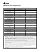
Electrical Connections
Make wiring connections to the unit as indicated on enclosed wiring diagram. As with all gas appliances using electrical power, this furnace shall
be connected into a permanently live electric circuit. It is recommended that furnace be provided with a separate "circuit protection device"
electric circuit. The furnace must be electrically grounded in accordance with local codes or in the absence of local codes with the National
Electrical Code, ANSI/NFPA 70 or CSA C22.1 Electrical Code, if an external electrical source is utilized. The integrated furnace control is
polarity sensitive. The hot leg of the 120V power supply must be connected to the black power lead as indicated on the wiring diagram.
Refer to the SERVICE FACTS literature and unit wiring diagram attached to furnace.
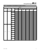
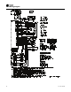
Field Wiring
O
BK
BK
Y2
Y1 Y1
B/C B/C
W2
W1W1
GG
RR
O
Y1
B/C
Two Stage
Thermostat
Furnace
Furnace IFC
Outdoor Unit
(No Transformer)
SEE
NOTE 2
BK JUMPER
SEE NOTE 1
Y2
W2
Y2
FIELD WIRING DIAGRAM FOR
TWO STAGE HEATING THERMOSTAT, TWO STAGE COOLING
NOTES:
1) For PWM (BK) enabled thermostats, cut the BK jumper
on the IFC and connect wiring.
2) The factory Y1-O jumper must remain in place for proper
LED read out in cooling mode.
3) Y1 and Y2 wiring from the thermostat must connect to
the IFC for proper airflow and LED readout.
4) Single compressor and two compressor airflow is auto-
matically set with the IFC Menu optionsin ODU section.
2-1=2 stage / 1 compressor (1st stage airflow = 75%)
2-2=2 stage / 2 compressors (1st stage airflow = 50%)
INTER-COMPONENT WIRING
24 V FIELD WIRING
24 V FACTORY WIRING
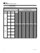
O
BK
BK
Y2
Y1 Y1
B/C B/C
W2W2
W1W1
GG
RR
O
Y1
Two Stage
Thermostat
Furnace
Outdoor Unit
(No Transformer)
SEE
NOTE 2
O
R
X2
Y2
NOTES:
1) For PWM (BK) enabled thermostats, cut the BK jumper
on the IFC and connect wiring.
2) Remove the factory Y1-O jumper for HP systems
for proper LED read out.
3) Y1 and Y2 wiring from the thermostat must connect to Y1 and
Y2 of the IFC for proper airflow and LED readout.
4) Single compressor and two compressor airflow is automatically
set with the IFC Menu options in ODU section.
2-1=2 stage / 1 compressor (1st stage airflow = 75%)
2-2=2 stage / 2 compressors (1st stage airflow = 50%)
INTER-COMPONENT WIR
ING
24 V FIELD WIRING
24 V FACTORY WIRING
R-BK
JUMPER
SEE NOTE 1
Furnace IFC
FIELD WIRING DIAGRAM FOR
TWO STAGE HEATING THERMOSTAT, TWO STAGE HEAT PUMP
Y2
B/C