Product Data Upflow/ Horizontal Left/Right, Downflow Two Stage Condensing Gas Fired Furnace Upflow, Convertible to Horizontal Right or Horizontal Left S9V2B040U3PSBA S9V2B060U3PSBA S9V2B060U4PSBA S9V2B080U3PSBA S9V2B080U4PSBA S9V2C080U5PSBA S9V2C100U4PSBA S9V2C100U5PSBA S9V2D120U5PSBA Downflow Only S9V2B040D3PSBA S9V2B060D3PSBA S9V2B080D3PSBA S9V2B080D4PSBA S9V2C100D4PSBA S9V2C100D5PSBA S9V2D120D5PSBA N o t e : Graphics in this document are for representation only. Actual model may differ in appearance.
General Features NATURAL GAS MODELS Central Heating furnace designs are certified by the American Gas Association for both natural and L.P. gas. Limit setting and rating data were established and approved under standard rating conditions using American National Standards Institute standards. SAFE OPERATION The Integrated System Control is a solid state device which continuously monitors for presence of flame when the system is in the heating mode of operation.
Features and Benefits 96.
Features and Benefits THREE–WAY MULTI-POISE (UPFLOW, HORIZONTAL LEFT AND RIGHT) PLUS DEDICATED DOWNFLOW Easier to specify Shipped ready to install (no kits required) Every model has at least two venting options When in horizontal, trap extends only about 2” Barbed fitting on trap at hose connection and on cabinet transition for hose has barbed fitting and clamps at both ends for leak resistance.
Accessories Table 1.
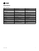
Product Specification S9V2B040U3PSBA (a) S9V2B060U3PSBA(a) MODEL S9V2B060U4PSBA(a) S9V2B080U3PSBA(a) Upflow/Horizontal Upflow/Horizontal Upflow/Horizontal Upflow / Horizontal 1st Stage Input BTUH (ICS) 26,000 39,000 39,000 52,000 1st Stage Capacity BTUH 25,220 37,830 37,830 50,440 40,000 60,000 60,000 80,000 TYPE RATINGS (b) 2nd Stage Input BTUH 2nd Stage Capacity BTUH (ICS) 38,800 58,200 58,200 77,600 1st Stage Temp. Rise (Min.-Max.
Product Specification S9V2B040U3PSBA (a) S9V2B060U3PSBA(a) MODEL S9V2B060U4PSBA(a) S9V2B080U3PSBA(a) Max. Overcurrent Protection (Amps) 15 15 15 15 PIPE CONN. SIZE (in.) 1/2 1/2 1/2 1/2 DIMENSIONS Uncrated (In.) Crated (In.) HxWxD HxWxD HxWxD HxWxD 34 x 17-1/2 x 28–3/4 34 x 17-1/2 x 28–3/4 34 x 17-1/2 x 28–3/4 34 x 17-1/2 x 28–3/4 35-1/2 x 19-1/2 x 30-7/8 35-1/2 x 19-1/2 x 30-7/8 35-1/2 x 19-1/2 x 30-7/8 35-1/2 x 19-1/2 x 30-7/8 WEIGHT Shipping (Lbs.)/Net (Lbs.
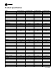
Product Specification S9V2B080U4PSBA (a) S9V2C080U5PSBA(a) MODEL Gauge (Fired) S9V2C100U4PSBA(a) S9V2C100U5PSBA(a) 20 20 20 20 Nat. Gas Qty. — Drill Size 4 - 45 4 - 45 5 - 45 5 - 45 LP Gas Qty.
Product Specification MODEL Drive — No. Speeds S9V2D120U5PSBA (a) S9V2B040D3PSBA(a) S9V2B060D3PSBA(a) S9V2B080D3PSBA(a) Direct - 2 Direct - 2 Direct - 2 Direct - 2 Motor HP — RPM 3300/2600 3300/2600 3300/2600 3300/2600 Volts/Ph/Hz 120 / 1 / 60 120 / 1 / 60 120 / 1 / 60 120 / 1 / 60 0.66 0.66 0.66 0.66 FLA FILTER — Furnished? Type recommended Hi Vel. (No.-Size-Thk.) VENT PIPE DIAMETER — Min (in.
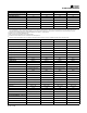
Product Specification S9V2B080D4PSBA (a) S9V2C100D4PSBA(a) MODEL TYPE S9V2C100D5PSBA(a) S9V2D120D5PSBA(a) Downflow Downflow Downflow Downflow 1st Stage Input BTUH (ICS) 52,000 65,000 65,000 78,000 1st Stage Capacity BTUH 50,440 63,050 63,050 75,660 2nd Stage Input BTUH 80,000 100,000 100,000 120,000 2nd Stage Capacity BTUH (ICS) (c) (d) 77,600 97,000 97,000 116,400 1st Stage Temp. Rise (Min.-Max.) 30 - 60 25 - 55 25 - 55 35-65 2nd Stage Temp. Rise (Min.-Max.
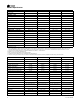
Product Specification MODEL DIMENSIONS Uncrated (In.) Crated (In.) S9V2B080D4PSBA (a) S9V2C100D4PSBA(a) S9V2C100D5PSBA(a) S9V2D120D5PSBA(a) HxWxD HxWxD HxWxD HxWxD 34 x 17-1/2 x 28–3/4 34 x 21 x 28–3/4 34 x 21 x 28–3/4 34 x 24-1/2 x 28–3/4 35-1/2 x 19-1/2 x 30-7/8 35-1/2 x 23 x 30-7/8 35-1/2 x 23 x 30-7/8 35-1/2 x 26-1/2 x 30-7/8 135/127 154/144 155/145 167/156 WEIGHT Shipping (Lbs.)/Net (Lbs.) (a) (b) (c) (d) (e) (f) (g) Meets Energy Star For U.S.
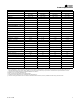
Heating and Cooling Airflow Tables S9V2B040U3PSBA Table 2. S9V2B040U3PSBA Heating Airflow S9V2B040U3PSBA Furnace Heating Airflow (CFM) and Power (Watts) vs. External Static Pressure with Filter 1st Stage Capacity = 25,220 2nd Stage Capacity = 38,800 Airflow Setting Heating Low 468 Medium Low 598 Heating 1st Stage Medium (a) High 634 1008 Low 650 Medium Low 830 Heating 2nd Stage Medium High (a) 12 (a) External Static Pressure Target Airflow 880 1400 0.1 0.3 0.5 0.7 0.
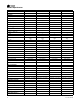
Heating and Cooling Airflow Tables S9V2B040D3PSBA Table 3. S9V2B040D3PSBA Heating Airflow S9V2B040D3PSBA Furnace Heating Airflow (CFM) and Power (Watts) vs. External Static Pressure with Filter 1st Stage Capacity = 25,220 2nd Stage Capacity = 38,800 Airflow Setting Heating Low Medium Low 468 598 Heating 1st Stage Medium (a) High Low Medium Low 634 1008 650 830 Heating 2nd Stage Medium (a) High (a) External Static Pressure Target Airflow 880 1400 0.1 0.3 0.5 0.7 0.
Heating and Cooling Airflow Tables S9V2B040U3PSBA / S9V2B040D3PSBA Table 4. S9V2B040U3PSBA / S9V2B040D3PSBA Cooling Airflow S9V2B040U3PSBA / S9V2B040D3PSBA Furnace Cooling Airflow (CFM) and Power (Watts) vs.
Heating and Cooling Airflow Tables Table 4. S9V2B040U3PSBA / S9V2B040D3PSBA Cooling Airflow (continued) S9V2B040U3PSBA / S9V2B040D3PSBA Furnace Cooling Airflow (CFM) and Power (Watts) vs. External Static Pressure with Filter Cooling Unit Outdoor Airflow Setting (CFM/ ton) Cooling 400 CFM/Ton Cooling 370 CFM/Ton Cooling 350 CFM/Ton Cooling 330 CFM/Ton Cooling 310 CFM/Ton Cooling 290 CFM/Ton Cooling 450 CFM/Ton Cooling 420 CFM/Ton Cooling 400 CFM/Ton Cooling 370 CFM/Ton Cooling 0.1 0.3 0.5 0.7 0.
Heating and Cooling Airflow Tables S9V2B060U3PSBA Table 5. S9V2B060U3PSBA Heating Airflow S9V2B060U3PSBA Furnace Heating Airflow (CFM) and Power (Watts) vs. External Static Pressure with Filter 1st Stage Capacity = 37,830 2nd Stage Capacity = 58,200 Airflow Setting Heating Low Medium Low (a) 632 814 Heating 1st Stage Medium High Low Medium Low (a) 893 1153 800 1030 Heating 2nd Stage Medium High (a) 16 External Static Pressure Target Airflow 1130 1460 0.1 0.3 0.5 0.7 0.
Heating and Cooling Airflow Tables S9V2B060D3PSBA Table 6. S9V2B060D3PSBA Heating Airflow S9V2B060D3PSBA Furnace Heating Airflow (CFM) and Power (Watts) vs. External Static Pressure with Filter 1st Stage Capacity = 37,830 2nd Stage Capacity = 58,200 Airflow Setting Heating Low Medium Low (a) 632 814 Heating 1st Stage Medium High Low Medium Low (a) 893 1153 800 1030 Heating 2nd Stage Medium High (a) External Static Pressure Target Airflow 1130 1460 0.1 0.3 0.5 0.7 0.
Heating and Cooling Airflow Tables S9V2B060U3PSBA / S9V2B060D3PSBA Table 7. S9V2B060U3PSBA / S9V2B060D3PSBA Cooling Airflow S9V2B060U3PSBA / S9V2B060D3PSBA Furnace Cooling Airflow (CFM) and Power (Watts) vs.
Heating and Cooling Airflow Tables Table 7. S9V2B060U3PSBA / S9V2B060D3PSBA Cooling Airflow (continued) S9V2B060U3PSBA / S9V2B060D3PSBA Furnace Cooling Airflow (CFM) and Power (Watts) vs. External Static Pressure with Filter Cooling Unit Outdoor Airflow Setting (CFM/ ton) Cooling 400 CFM/Ton Cooling 370 CFM/Ton Cooling 350 CFM/Ton Cooling 330 CFM/Ton Cooling 310 CFM/Ton Cooling 290 CFM/Ton Cooling 450 CFM/Ton Cooling 420 CFM/Ton Cooling 400 CFM/Ton Cooling 370 CFM/Ton Cooling 0.1 0.3 0.5 0.7 0.
Heating and Cooling Airflow Tables S9V2B060U4PSBA Table 8. S9V2B060U4PSBA Heating Airflow S9V2B060U4PSBA Furnace Heating Airflow (CFM) and Power (Watts) vs. External Static Pressure with Filter 1st Stage Capacity = 37,830 2nd Stage Capacity = 58,200 Airflow Setting Heating Low Medium Low 782 861 Heating 1st Stage Medium (a) High Low Medium Low 916 1256 990 1090 Heating 2nd Stage Medium (a) High (a) 20 External Static Pressure Target Airflow 1160 1590 0.1 0.3 0.5 0.7 0.
Heating and Cooling Airflow Tables S9V2B060U4PSBA Table 9. S9V2B060U4PSBA Cooling Airflow S9V2B060U4PSBA Furnace Cooling Airflow (CFM) and Power (Watts) vs.
Heating and Cooling Airflow Tables Table 9. S9V2B060U4PSBA Cooling Airflow (continued) S9V2B060U4PSBA Furnace Cooling Airflow (CFM) and Power (Watts) vs. External Static Pressure with Filter Cooling Unit Outdoor Cooling 400 CFM/Ton Cooling 370 CFM/Ton Cooling 350 CFM/Ton Cooling 330 CFM/Ton Cooling 310 CFM/Ton Cooling 290 CFM/Ton Cooling 450 CFM/Ton Cooling 420 CFM/Ton Cooling 400 CFM/Ton Cooling 370 CFM/Ton Cooling Cooling 330 CFM/Ton Cooling 310 CFM/Ton Cooling 290 CFM/Ton 22 CFM 0.1 0.3 0.5 0.
Heating and Cooling Airflow Tables S9V2B080U3PSBA Table 10. S9V2B080U3PSBA Heating Airflow S9V2B080U3PSBA Furnace Heating Airflow (CFM) and Power (Watts) vs. External Static Pressure with Filter 1st Stage Capacity = 50,440 2nd Stage Capacity = 77,600 Airflow Setting Heating Low Medium Low 948 1051 Heating 1st Stage Medium (a) High Low Medium Low 1090 1168 1200 1330 Heating 2nd Stage Medium (a) High (a) External Static Pressure Target Airflow 1380 1480 0.1 0.3 0.5 0.7 0.
Heating and Cooling Airflow Tables S9V2B080D3PSBA Table 11. S9V2B080D3PSBA Heating Airflow S9V2B080D3PSBA Furnace Heating Airflow (CFM) and Power (Watts) vs. External Static Pressure with Filter 1st Stage Capacity = 50,440 2nd Stage Capacity = 77,600 Airflow Setting Heating Low Medium Low 948 1051 Heating 1st Stage Medium (a) High Low Medium Low 1090 1168 1200 1330 Heating 2nd Stage Medium (a) High (a) 24 External Static Pressure Target Airflow 1380 1480 0.1 0.3 0.5 0.7 0.
Heating and Cooling Airflow Tables S9V2B080U3PSBA / S9V2B080D3PSBA Table 12. S9V2B080U3PSBA / S9V2B080D3PSBA Cooling Airflow S9V2B080U3PSBA / S9V2B080D3PSBA Furnace Cooling Airflow (CFM) and Power (Watts) vs.
Heating and Cooling Airflow Tables Table 12. S9V2B080U3PSBA / S9V2B080D3PSBA Cooling Airflow (continued) S9V2B080U3PSBA / S9V2B080D3PSBA Furnace Cooling Airflow (CFM) and Power (Watts) vs.
Heating and Cooling Airflow Tables S9V2B080U4PSBA Table 13. S9V2B080U4PSBA Heating Airflow S9V2B080U4PSBA Furnace Heating Airflow (CFM) and Power (Watts) vs. External Static Pressure with Filter 1st Stage Capacity = 50,440 2nd Stage Capacity = 77,600 Airflow Setting Heating Low Medium Low (a) 864 907 Heating 1st Stage Medium High Low Medium Low (a) 958 1051 1200 1260 Heating 2nd Stage Medium High (a) External Static Pressure Target Airflow 1330 1460 0.1 0.3 0.5 0.7 0.
Heating and Cooling Airflow Tables S9V2B080D4PSBA Table 14. S9V2B080D4PSBA Heating Airflow S9V2B080D4PSBA Furnace Heating Airflow (CFM) and Power (Watts) vs. External Static Pressure with Filter 1st Stage Capacity = 50,440 2nd Stage Capacity = 77,600 Airflow Setting Heating Low Medium Low (a) 864 907 Heating 1st Stage Medium High Low Medium Low (a) 958 1051 1200 1260 Heating 2nd Stage Medium High (a) 28 External Static Pressure Target Airflow 1330 1460 0.1 0.3 0.5 0.7 0.
Heating and Cooling Airflow Tables S9V2B080U4PSBA / S9V2B080D4PSBA Table 15. S9V2B080U4PSBA / S9V2B080D4PSBA Cooling Airflow S9V2B080U4PSBA / S9V2B080D4PSBA Furnace Cooling Airflow (CFM) and Power (Watts) vs.
Heating and Cooling Airflow Tables Table 15. S9V2B080U4PSBA / S9V2B080D4PSBA Cooling Airflow (continued) S9V2B080U4PSBA / S9V2B080D4PSBA Furnace Cooling Airflow (CFM) and Power (Watts) vs.
Heating and Cooling Airflow Tables S9V2C080U5PSBA Table 16. S9V2C080U5PSBA Heating Airflow S9V2C080U5PSBA Furnace Heating Airflow (CFM) and Power (Watts) vs. External Static Pressure with Filter 1st Stage Capacity = 50,440 2nd Stage Capacity = 77,600 Airflow Setting Heating Low Medium Low (a) 857 1044 Heating 1st Stage Medium High Low Medium Low (a) 1123 1498 1190 1450 Heating 2nd Stage Medium High (a) External Static Pressure Target Airflow 1560 2080 0.1 0.3 0.5 0.7 0.
Heating and Cooling Airflow Tables S9V2C080U5PSBA Table 17. S9V2C080U5PSBA Cooling Airflow S9V2C080U5PSBA Furnace Cooling Airflow (CFM) and Power (Watts) vs.
Heating and Cooling Airflow Tables Table 17. S9V2C080U5PSBA Cooling Airflow (continued) S9V2C080U5PSBA Furnace Cooling Airflow (CFM) and Power (Watts) vs. External Static Pressure with Filter Cooling Unit Outdoor Cooling 400 CFM/Ton Cooling 370 CFM/Ton Cooling 350 CFM/Ton Cooling 330 CFM/Ton Cooling 310 CFM/Ton Cooling 290 CFM/Ton Cooling 450 CFM/Ton Cooling 420 CFM/Ton Cooling 400 CFM/Ton Cooling 370 CFM/Ton Cooling 0.1 0.3 0.5 0.7 0.
Heating and Cooling Airflow Tables S9V2C100U4PSBA Table 18. S9V2C100U4PSBA Heating Airflow S9V2C100U4PSBA Furnace Heating Airflow (CFM) and Power (Watts) vs. External Static Pressure with Filter 1st Stage Capacity = 63,050 2nd Stage Capacity = 97,000 Airflow Setting Heating Low Medium Low 1146 1280 Heating 1st Stage Medium (a) High Low Medium Low 1446 1493 1450 1620 Heating 2nd Stage Medium (a) High (a) 34 External Static Pressure Target Airflow 1830 1890 0.1 0.3 0.5 0.7 0.
Heating and Cooling Airflow Tables S9V2C100D4PSBA Table 19. S9V2C100D4PSBA Heating Airflow S9V2C100D4PSBA Furnace Heating Airflow (CFM) and Power (Watts) vs. External Static Pressure with Filter 1st Stage Capacity = 63,050 2nd Stage Capacity = 97,000 Airflow Setting Heating Low Medium Low 1080 1166 Heating 1st Stage Medium (a) High Low Medium Low 1318 1361 1500 1620 Heating 2nd Stage Medium (a) High (a) External Static Pressure Target Airflow 1830 1890 0.1 0.3 0.5 0.7 0.
Heating and Cooling Airflow Tables S9V2C100U4PSBA / S9V2C100D4PSBA Table 20. S9V2C100U4PSBA / S9V2C100D4PSBA Cooling Airflow S9V2C100U4PSBA / S9V2C100D4PSBA Furnace Cooling Airflow (CFM) and Power (Watts) vs.
Heating and Cooling Airflow Tables Table 20. S9V2C100U4PSBA / S9V2C100D4PSBA Cooling Airflow (continued) S9V2C100U4PSBA / S9V2C100D4PSBA Furnace Cooling Airflow (CFM) and Power (Watts) vs. External Static Pressure with Filter Cooling Unit Outdoor Airflow Setting (CFM/ ton) Cooling 400 CFM/Ton Cooling 370 CFM/Ton Cooling 350 CFM/Ton Cooling 330 CFM/Ton Cooling 310 CFM/Ton Cooling 290 CFM/Ton Cooling 450 CFM/Ton Cooling 420 CFM/Ton Cooling 400 CFM/Ton Cooling 370 CFM/Ton Cooling 0.1 0.3 0.5 0.7 0.
Heating and Cooling Airflow Tables S9V2C100U5PSBA Table 21. S9V2C100U5PSBA Heating Airflow S9V2C100U5PSBA Furnace Heating Airflow (CFM) and Power (Watts) vs. External Static Pressure with Filter 1st Stage Capacity = 63,050 2nd Stage Capacity = 97,000 Airflow Setting Heating Low Medium Low (a) 1145 1426 Heating 1st Stage Medium High Low Medium Low (a) 1548 1620 1590 1980 Heating 2nd Stage Medium High (a) 38 External Static Pressure Target Airflow 2150 2250 0.1 0.3 0.5 0.7 0.
Heating and Cooling Airflow Tables S9V2C100D5PSBA Table 22. S9V2C100D5PSBA Heating Airflow S9V2C100D5PSBA Furnace Heating Airflow (CFM) and Power (Watts) vs. External Static Pressure with Filter 1st Stage Capacity = 63,050 2nd Stage Capacity = 97,000 Airflow Setting Heating Low Medium Low 1094 1296 Heating 1st Stage Medium (a) High Low Medium Low 1346 1620 1520 1800 Heating 2nd Stage Medium (a) High (a) External Static Pressure Target Airflow 1870 2250 0.1 0.3 0.5 0.7 0.
Heating and Cooling Airflow Tables S9V2C100U5PSBA / S9V2C100D5PSBA Table 23. S9V2C100U5PSBA / S9V2C100D5PSBA Cooling Airflow S9V2C100U5PSBA / S9V2C100D5PSBA Furnace Cooling Airflow (CFM) and Power (Watts) vs.
Heating and Cooling Airflow Tables Table 23. S9V2C100U5PSBA / S9V2C100D5PSBA Cooling Airflow (continued) S9V2C100U5PSBA / S9V2C100D5PSBA Furnace Cooling Airflow (CFM) and Power (Watts) vs. External Static Pressure with Filter Cooling Unit Outdoor Airflow Setting (CFM/ ton) Cooling 400 CFM/Ton Cooling 370 CFM/Ton Cooling 350 CFM/Ton Cooling 330 CFM/Ton Cooling 310 CFM/Ton Cooling 290 CFM/Ton Cooling 450 CFM/Ton Cooling 420 CFM/Ton Cooling 400 CFM/Ton Cooling 370 CFM/Ton Cooling 0.1 0.3 0.5 0.7 0.
Heating and Cooling Airflow Tables S9V2D120U5PSBA Table 24. S9V2D120U5PSBA Heating Airflow S9V2D120U5PSBA Furnace Heating Airflow (CFM) and Power (Watts) vs. External Static Pressure with Filter 1st Stage Capacity = 75,660 2nd Stage Capacity = 116,400 Airflow Setting Heating Low Medium Low 1123 1332 Heating 1st Stage Medium (a) High Low Medium Low 1404 1620 1560 1850 Heating 2nd Stage Medium (a) High (a) 42 External Static Pressure Target Airflow 1950 2250 0.1 0.3 0.5 0.7 0.
Heating and Cooling Airflow Tables S9V2D120D5PSBA Table 25. S9V2D120D5PSBA Heating Airflow S9V2D120D5PSBA Furnace Heating Airflow (CFM) and Power (Watts) vs. External Static Pressure with Filter 1st Stage Capacity = 75,660 2nd Stage Capacity = 116,400 Airflow Setting Heating Low Medium Low 1160 1332 Heating 1st Stage Medium High (a) Low Medium Low 1404 1620 1750 1850 Heating 2nd Stage Medium High (a) (a) External Static Pressure Target Airflow 1950 2250 0.1 0.3 0.5 0.7 0.
Heating and Cooling Airflow Tables S9V2D120U5PSBA / S9V2D120D5PSBA Table 26. S9V2D120U5PSBA / S9V2D120D5PSBA Cooling Airflow S9V2D120U5PSBA / S9V2D120D5PSBA Furnace Cooling Airflow (CFM) and Power (Watts) vs.
Heating and Cooling Airflow Tables Table 26. S9V2D120U5PSBA / S9V2D120D5PSBA Cooling Airflow (continued) S9V2D120U5PSBA / S9V2D120D5PSBA Furnace Cooling Airflow (CFM) and Power (Watts) vs. External Static Pressure with Filter Cooling Unit Outdoor Airflow Setting (CFM/ ton) Cooling 400 CFM/Ton Cooling 370 CFM/Ton Cooling 350 CFM/Ton Cooling 330 CFM/Ton Cooling 310 CFM/Ton Cooling 290 CFM/Ton Cooling 450 CFM/Ton Cooling 420 CFM/Ton Cooling 400 CFM/Ton Cooling 370 CFM/Ton Cooling 0.1 0.3 0.5 0.7 0.
Maximum Vent Length Table Maximum Total Equivalent Length In Feet for Vent and Inlet Air (See Notes) Maximum Vent Length Table Model 2 Inch or 2.
S9V2 Wiring Diagram S9V2 Wiring Diagram and Schematic 22-1921-1C-EN 47
S9V2 Wiring Diagram 48 22-1921-1C-EN
Electrical Connections Make wiring connections to the unit as indicated on enclosed wiring diagram. As with all gas appliances using electrical power, this furnace shall be connected into a permanently live electric circuit. It is recommended that furnace be provided with a separate "circuit protection device" electric circuit. The furnace must be electrically grounded in accordance with local codes or in the absence of local codes with the National Electrical Code, ANSI/NFPA 70 or CSA C22.
Electrical Connections Single Stage Thermostat Furnace BK BK FIELD WIRING DIAGRAM FOR SINGLE STAGE HEATING THERMOSTAT, SINGLE STAGE COOLING W2 SEE NOTE 4 W1 W1 R R Outdoor Unit (No Transformer) G G B/C B/C B/C Y2 Y1 Y1 Y1 O O NOTES: 1) For PWM (BK) enabled thermostats, cut the BK jumper on the IFC and connect wiring. 2) The factory Y1-O jumper must remain in place for proper LED read out in cooling mode.
Outline Drawings 22-1921-1C-EN 51
Outline Drawings 52 22-1921-1C-EN
Outline Drawings 22-1921-1C-EN 53
Outline Drawings 54 22-1921-1C-EN
Outline Drawings 22-1921-1C-EN 55
Outline Drawings 56 22-1921-1C-EN
Notes 22-1921-1C-EN 57
Notes 58 22-1921-1C-EN
Notes 22-1921-1C-EN 59
Ingersoll Rand (NYSE: IR) advances the quality of life by creating comfortable, sustainable and efficient environments. Our people and our family of brands — including Club Car®, Ingersoll Rand®, Thermo King® and Trane® — work together to enhance the quality and comfort of air in homes and buildings; transport and protect food and perishables; and increase industrial productivity and efficiency. We are a global business committed to a world of sustainable progress and enduring results. ingersollrand.