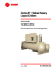
Series R™ Helical Rotary Liquid Chillers Model RTHD 175-450Tons (60 Hz) 125-450Tons (50 Hz) Built for Industrial and Commercial Applications June 2006 RLC-PRC020-EN
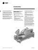
Introduction To meet a wide range of applications in the medium-tonnage, water-cooled market,Trane is proud to introduce the model RTHD helical rotary liquid chiller. The introduction of this next-generation chiller an exciting step forward in application versatility, ease of installation, control precision, reliability, energyefficiency, and operational cost-effectiveness.
Contents RLC-PRC020-EN Introduction 2 Features and Benefits 4 Options 6 Controls 8 Application Considerations 10 Selection Procedure 12 Model Nomenclature 14 General Data 16 Electrical Data and Connections 19 Dimensions and Weights 22 Mechanical Specifications 29 Conversion Table 30 3
Features and Benefits Application Versatility and High Performance • Screw compressor technology and the electronic expansion valve provide reliable performance in an expanded range of operating temperatures. •Tight water temperature control extends to operation of multiple chillers in parallel or series configurations, offering further system design flexibility for maximum efficiency. • Advanced design enables chilled water temperature control to +/- 0.5°F (.
Features and Benefits State-of-the-Art, Precision Control • Microprocessor-based CH530 controls monitor and maintain optimal operation of the chiller and its associated sensors, actuators, relays, and switches, all of which are factory-assembled and extensively tested. • Easy interface with computers hosting Tracer Summit™ building automation/ energy management systems allows the operator to efficiently optimize comfort system performance and minimize operating costs.
Options Insulation All low temperature surfaces are covered with factory installed 3/4 inch (19.05 mm) Armaflex II or equal (k=0.28) insulation, including the evaporator and water boxes, suction line, and motor housing. 3/8" foam insulation is used on the liquid level sensor and gas pump assembly, including piping. Low-Temperature Evaporator Addition of an oil cooler to the oil circuit enables evaporator operation down to minimum leaving water temperature of 10°F (-12.2°C).
Options Control Options: Tracer Summit Communications Link to factory-installed, tested communication board, via single twistedpair wiring, addsTracer Summit communications to the system. LonTalk LCI-C Interface LonTalk (LCI-C) communications capabilities are available, with communication link via single twisted-pair wiring to factory-installed, tested communication board.
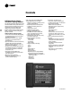
Controls LCD Touch-Screen Display with Multi-Language Support The standard DynaView display provided with the CH530 control panel features an LCD touch-screen, allowing access to all operational inputs and outputs.This display supports eleven languages: English, Chinese, Dutch, French, German, Italian, Japanese, Korean, Portugese, Spanish andThai.
Controls Trane Chiller Plant Automation Trane’s depth of experience in chillers and controls makes us a well-qualified choice for automation of chiller plants using aircooled Series R® chillers®.The chiller plant control capabilities of theTraneTracer Summit® building automation system are unequaled in the industry. Our chiller plant automation software is fully preengineered and tested.
Application Considerations Condenser Water Temperatures Reduced sensitivity to condenser water startup temperatures is one major enhancement in the newest-generation water-cooled Series R chiller. With the model RTHD chiller, a condenser water control method is necessary only if the unit starts with entering water temperatures below 55°F (12.8°C), or between 45°F (7.2°C) and 55°F (12.8°C), when a temperature increase of 1°F (0.56°C) per minute to 55°F (12.8°) is not possible.
Application Considerations Series Chiller Arrangements Another energy-saving strategy is to design the system around chillers arranged in series, on the evaporator, condenser, or both.The actual savings possible with such strategies depends on the application dynamics and should be researched by consulting yourTrane Systems Solutions Representative and applying theTrane System Analyzer program.
Selection Procedure Trane Series R chiller performance is rated in accordance with the ARI Standard 550/590-2003 Certification Program. Chiller selection assistance and performance information can be obtained by using the Series R chiller selection program, available through local Trane sales offices. Performance The computerized Series R chiller selection program provides performance data for each possible chiller selection at both full-load and part-load design points, as required.
Selection Procedure Unit Performance with Fluid Media Other Than Water Series R chillers can be provided with a wide variety of fluid media other than water, including ethylene glycol and propylene glycol— in the evaporator, condenser or both. Chillers using media other than water are excluded from the ARI 550/590-2003 Certification Program, but are rated in accordance with ARI Standard 550/590-2003. Trane factory performance tests are only performed with water as the cooling and heatrejection media.
Model Nomenclature RTH D 1,2,3 4 U 5 D 6 2 7 F 8 Digits 01, 02, 03 – Series R™ RTH = Series R Digit 04 – Dev Sequence D = 4th Major Development Digit 05 – Design Control U = WCBU Digit 06 – Compressor Frame B = B Compressor C = C Compressor D = D Compressor E = E Compressor Digit 07 – Compressor Capacity 1 = Smaller Capacity for Frame 2 = Larger Capacity for Frame 3 = 50Hz Capacity Digit 08 – Unit Power Supply A = 200V/60Hz/3Ph power C = 230V/60Hz/3Ph power D = 380V/60Hz/3Ph power R = 380V/50Hz/3Ph po
Model Nomenclature A V 28 29 X 30 Q 31 X 32 E 33 X A 34 35 A 36 Digit 28 – Condenser Leaving Water Temperature A = Standard Digit 29 – Refrigerant Specialties X = No Refrigerant Isolation Valves V = With Refrigerant Isolation Valves Digit 30 – Oil Cooler X = Without Oil Cooler C = With Oil Cooler Digit 31 – Thermal Insulation X = No Insulation Q = Factory Installed Insulation Digit 32 – Acoustic Insulation X = No Insulation A = Standard Insulation B 37 D 38 Y 444 D 39 40,41,42 43 A 44 X 45 A 4
General Data Nominal Data Nominal Compressor B1 Tonnage (60 Hz) 175-200 Tonnage (50 Hz) 125-150 B2 200-225 150-175 C1 225-275 175-225 C2 275-325 225-275 D1 325-400 275-325 D2 375-450 300-350 D3 E3 N/A N/A 325-375 375-450 Notes: 1. Chiller selections can be optimized through the use of the ARI-Certified Series R selection program and by contacting your local Trane sales office.
General Data Water Flow Rates Minimum/Maximum Evaporator Flow Rates (Gallons/Minute ) Two Pass Evaporator Code B1 B2 C1 C2 D1 D2 D3 D4 D5 D6 E1 F1 F2 G1 G2 G3 Min 253 288 320 347 415 450 486 351 351 293 450 563 604 ———- Max 1104 1266 1412 1531 1812 1980 2131 1542 1542 1287 1980 2478 2667 ———- Three Pass Nominal Conn Size (In.
General Data Brine Flow Rates Minimum/Maximum Evaporator Flow Rates (GPM) Two Pass Evaporator Code B1 B2 C1 C2 D1 D2 D3 D4 D5 D6 E1 F1 F2 G1 G2 G3 Min 303 346 346 375 498 541 584 422 422 352 487 676 725 ———- Max 1104 1266 1412 1531 1812 1980 2131 1542 1542 1287 1980 2478 2667 ———- Three Pass Nominal Conn Size (In.
Electrical Data and Connections Compressor Motor Electrical Data (60 Hertz) Compressor Code B1, B2 C1, C2 D1, D2 Nominal Voltage Voltage Utilization Range Max kW RLA @ Max kW LRAY LRAD Max kW RLA @ Max kW LRAY LRAD Max kW RLA @ Max kW LRAY LRAD 200 180/ 220 174 557 970 3103 249 812 1173 3634 329 888 1690 5477 230 208/ 254 174 484 818 2617 249 698 936 2901 329 888 1532 4966 380 342/ 418 174 291 488 1561 249 421 558 1727 329 549 850 2755 460 414/ 506 174 241 400 1280 249 349 469 1453 329 455 730 2366
Electrical Data and Connections 20 RLC-PRC020-EN
Electrical Data and Connections RLC-PRC020-EN 21
Dimensions and Weights Shipping and Operating Weights Compressor Code B1 B1 B2 B2 C1 C1 C1 C2 C2 C2 D1 D1 D1 D1 D2, D3 D2, D3 D2, D3 D2, D3 E3 E3 E3 E3 Evaporator Code B1 C1 B2 C2 D6 D5 E1 D4 D3 F2 D1 F1 G1 G2 D2 F2 G2 G3 D2 F2 G2 G3 Condenser Code B1 D1 B2 D2 E5 E4 F1 E4 E3 F3 E1 F2 G1 G2 E2 F3 G1 G3 E2 F3 G1 G3 Operating Weight (lbs) (kg) 9,867 4,476 10,554 4,787 10,019 4,545 10,653 4,832 13,397 6,077 13,673 6,202 15,818 7,175 13,672 6,201 15,044 6,824 17,560 7,965 15,385 6,978 17,537 7,955 20,500 9,2
Dimensions and Weights BBB Configuration Recommended Clearances Front 36" (914 mm) Back 36" (914 mm) Either End 36" (914 mm) Other End* 108" (2743 mm) Top 36" (914 mm) * Clearance for tube removal Note: 1. Dimensions are based on 3 Pass Evap / 2 Pass Cond and LH/LH water connections. Refer to submittals for exact configuration. 2. Refer to the Nominal Capacity Data table in the General Data section for capacity ranges of each compressor.
Dimensions and Weights BCD Configuration Recommended Clearances Front 36" (914 mm) Back 36" (914 mm) Either End 36" (914 mm) Other End* 126" (3200 mm) Top 36" (914 mm) * Clearance for tube removal Note: 1. Dimensions are based on 3 Pass Evap / 2 Pass Cond and LH/LH water connections. Refer to submittals for exact configuration. 2. Refer to the Nominal Capacity Data table in the General Data section for capacity ranges of each compressor.
Dimensions and Weights CDE, DDE, EDE Configuration Recommended Clearances Front 36" (914 mm) Back 36" (914 mm) Either End 36" (914 mm) Other End* 108" (2743 mm) Top 36" (914 mm) * Clearance for tube removal Note: 1. Dimensions are based on 3 Pass Evap / 2 Pass Cond and LH/LH water connections. Refer to submittals for exact configuration. 2. Refer to the Nominal Capacity Data table in the General Data section for capacity ranges of each compressor.
Dimensions and Weights CEF Configuration Recommended Clearances Front 36" (914 mm) Back 36" (914 mm) Either End 36" (914 mm) Other End* 126" (3200 mm) Top 36" (914 mm) * Clearance for tube removal Note: 1. Dimensions are based on 3 Pass Evap / 2 Pass Cond and LH/LH water connections. Refer to submittals for exact configuration. 2. Refer to the Nominal Capacity Data table in the General Data section for capacity ranges of each compressor.
Dimensions and Weights CFF, DFF, EFF Configuration Recommended Clearances Front 36" (914 mm) Back 36" (914 mm) Either End 36" (914 mm) Other End* 126" (3200 mm) Top 36" (914 mm) * Clearance for tube removal Note: 1. Dimensions are based on 3 Pass Evap / 2 Pass Cond and LH/LH water connections. Refer to submittals for exact configuration. 2. Refer to the Nominal Capacity Data table in the General Data section for capacity ranges of each compressor.
Dimensions and Weights DGG, EGG Configuration Recommended Clearances Front 36" (914 mm) Back 36" (914 mm) Either End 36" (914 mm) Other End* 126" (3200 mm) Top 36" (914 mm) * Clearance for tube removal Note: 1. Dimensions are based on 3 Pass Evap / 2 Pass Cond and LH/LH water connections. Refer to submittals for exact configuration. 2. Refer to the Nominal Capacity Data table in the General Data section for capacity ranges of each compressor.
Mechanical Specifications General Exposed metal surfaces are painted with air-dry beige, direct-to-metal, singlecomponent paint. Each unit ships with full operating charges of refrigerant and oil. Molded neoprene isolation pads are supplied for placement under all support points. Startup and operator instruction by factory-trained service personnel are included. All water pass arrangements are available with grooved connections (150 or 300 psig waterside).
Conversion Table 30 RLC-PRC020-EN
RLC-PRC020-EN 31
Trane A business of American Standard Companies www.trane.com For more information, contact your local sales office or e-mail us at comfort@trane.com. Literature Order Number RLC-PRC020-EN File Number PL-RF-RLC-000-PRC020-EN-0606 Supersedes RLC-PRC020-EN-00406 Stocking Location Inland Trane has a policy of continuous product and product data improvement and reserves the right to change design and specifications without notice.