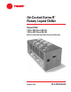
Air-Cooled Series R Rotary Liquid Chiller ™ Model RTAC 140 to 500 Tons (60 Hz) 140 to 400 Tons (50 Hz) Built For the Industrial and Commercial Markets August 2002 RLC-PRC006-EN
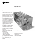
Introduction You… Figure 1 — Cutaway of RTAC Air-Cooled Chiller Like its chillers, Trane wants its relationships with customers to last. Trane is interested in maintaining long term, loyal relationships. This perspective means the point in time that a customer purchases a chiller is the beginning of a relationship, not the end. Your business is important, but your satisfaction is paramount. 4 Designed by Customers…. 1 Trane’s RTAC was designed with the end user’s requirements in mind.
Contents Introduction Features and Benefits 2 4 Options Application Considerations 9 Selection Procedure 13 Model Number Description 14 General Data 15 Performance Adjustment Factors 19 Performance Data 20 Full Load Performance Part Load Performance Electrical Data 34 Electrical Connections 46 Controls 51 Standalone Controls Generic Building Automation System Controls Trane Integrated Comfort System Controls RLC-PRC006-EN Dimensional Data 55 Wiring and Layout 65 Weights 74 Mec
Features and Benefits RTAC - Exceeding the Efficiency Standard 60 Hz Tonnage 140 155 170 185 200 225 250 275 300 350 400 450 500 ASHRAE 90.1 9.6 9.6 9.6 9.6 9.6 9.6 9.6 9.6 9.6 9.6 9.6 9.6 9.6 Full Load Efficiency (EER*) Standard Efficiency 9.7 9.8 9.9 9.7 9.6 9.6 9.6 9.7 9.6 9.6 9.6 9.6 9.6 High Efficiency 10.4 10.4 10.5 10.3 10.1 10.2 10.1 10.4 10.0 10.4 10.0 n/a n/a ASHRAE 90.1 10.4 10.4 10.4 10.4 10.4 10.4 10.4 10.4 10.4 10.4 10.4 10.4 10.4 Part Load Efficiency (EER*) Standard Efficiency 13.2 13.
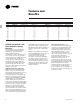
Features and Benefits Figure 2 — Cutaway of a compressor Excellent Reliability… A buildings environment is expected to be comfortable. When it is, no one says a word. If it’s not… that’s a different story. The same is true with chillers. No one ever talks about chillers, yet alone compressors, until they fail, and tenants are uncomfortable and productivity is lost. Trane’s helical rotary compressors have a first year reliability rate of over 99%, which means our chillers stay running when you need them.
Features and Benefits Simple Installation • Compact Physical Size. The Trane Model RTAC chiller averages a 20% reduction in physical footprint, while the greatest change is actually 40% smaller when compared against the previous design. This improvement makes the RTAC the smallest air-cooled chiller in the industry and a prime candidate for installations that have space constraints.
Features and Benefits Superior Control with Tracer™ Chiller Controllers The Adaptive Control™ microprocessor system enhances the air-cooled Series R chiller by providing the very latest chiller control technology. With the Adaptive Control microprocessor, unnecessary service calls and unhappy tenants are avoided. The unit is designed not to trip or unnecessarily shut down.
Features and Benefits High Efficiency/Performance Option This option provides oversized heat exchangers for two purposes. One, it allows the unit to be more energy efficient. Two, the unit will have enhanced operation in high ambient conditions. Access Protection A coated wire mesh that covers the access area under the condenser coils. Low Temperature Brine The hardware and software on the unit are factory set to handle low temperature brine applications (less than 40°F/4.4°C).
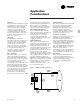
Application Considerations Important Certain application constraints should be considered when sizing, selecting and installing Trane air-cooled Series R chillers. Unit and system reliability is often dependent upon proper and complete compliance with these considerations. When the application varies from the guidelines presented, it should be reviewed with your local Trane sales engineer. Unit Sizing Unit capacities are listed in the performance data section.
Application Considerations Leaving Water Temperature Limits Trane air-cooled Series R chillers have three distinct leaving water categories: standard, low temperature, and ice making. The standard leaving solution temperature range is 40 to 60°F/4.4 to 15.6°C. Low temperature machines produce leaving liquid temperatures less than 40°F/4.4°C. Since liquid supply temperature setpoints less than 40°F/4.
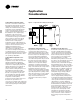
Application Considerations Ice Storage Provides Reduced Electrical Demand An ice storage system uses a standard chiller to make ice at night when utilities charge less for electricity. The ice supplements or even replaces mechanical cooling during the day when utility rates are at their highest. This reduced need for cooling results in big utility cost savings. Another advantage of ice storage is standby cooling capacity.
Application Considerations Short Water Loops The proper location of the temperature control sensor is in the supply (outlet) water connection or pipe. This location allows the building to act as a buffer and assures a slowly changing return water temperature. If there is not a sufficient volume of water in the system to provide an adequate buffer, temperature control can be lost, resulting in erratic system operation and excessive compressor cycling.
Selection Procedure The chiller capacity tables cover the most frequently encountered leaving liquid temperatures. The tables reflect a 10°F/5.6°C temperature drop through the evaporator. For other temperature drops, apply the appropriate Performance Data Adjustment Factors from Table A-1. For chilled brine selections, contact your local Trane sales engineer.
Model Number Description RT A C 350 A U CO N N A F N N 1 N 1,2 3 4 5,6,7 8 9 10,11 12 13 14 15 16 17 18 19 1140-500 Tons Digits 1, 2 — Unit Model RT Rotary Chiller Digit 3 — Unit Type A Air Cooled Digit 4 — Development Sequence C Third Sequence Digit 5, 6 & 7 — Nominal Capacity 140 140 Nominal Tons 155 155 Nominal Tons 170 170 Nominal Tons 185 185 Nominal Tons 200 200 Nominal Tons 225 225 Nominal Tons 250 250 Nominal Tons 275 275 Nominal Tons 300 300 Nominal Tons 350 350 Nominal Tons 375 375 Nominal Tons 4
General Data Table G-1 — General Data — 140-500 Ton 60 Hz Units - Standard Efficiency Size Type Compressor Quantity (1) 140 STD 155 STD 170 STD 185 STD 200 STD 225 STD 250 STD 275 STD 300 STD 350 STD 400 STD 450 STD 500 STD 2 2 2 2 2 2 2 Nominal Size (tons) Evaporator Water Storage 70/70 85/70 85/85 100/85 100/100 120/100 120/120 3 85-85 / 100 3 100-100 / 100 3 120-120 / 100 4 100-100 / 100-100 4 120-120 / 100-100 4 120-120 / 120-120 35 132 170 11 525 33 38 141 182 11 60
General Data Table G-1 —General Data — 140-400 Ton 60 Hz Units - High Efficiency Size Type Compressor Quantity (1) 140 HIGH 155 HIGH 170 HIGH 185 HIGH 200 HIGH 225 HIGH 250 HIGH 275 HIGH 300 HIGH 350 HIGH 400 HIGH 2 2 2 2 2 2 2 3 Nominal Size (tons) Evaporator Water Storage 70/70 85/70 85/85 100/85 100/100 120/100 120/120 85-85/100 3 100-100 / 100 4 85-85 / 85-85 4 100-100 / 100-100 40 151 198 13 687 43 42 156 215 14 626 39 43 163 215 14 767 48 47 176 237 15 848 54 50 18
General Data Table G-2 —General Data — 140-400 Ton 50 Hz Units-Standard Efficiency Size Type Compressor Quantity (1) 140 STD 155 STD 170 STD 185 STD 200 STD 250 STD 275 STD 300 STD 350 STD 375 STD 400 STD 2 2 2 2 2 Nominal Size (tons) Evaporator Water Storage 70/70 85/70 85/85 100/85 100/100 3 70-70 / 100 3 85-85 / 100 3 100-100 / 1100 4 85-85 / 85-85 4 100-100 / 85-85 4 100-100 / 100-100 35 132 171 11 525 33 38 141 182 11 606 38 40 151 198 13 684 43 42 156 215 14 626 39 44
General Data Table G-2 —General Data — 140-400 Ton 50 Hz Units-High Efficiency Size Type Compressor Quantity (1) 140 HIGH 155 HIGH 170 HIGH 185 HIGH 200 HIGH 250 HIGH 275 HIGH 300 HIGH 350 HIGH 375 HIGH 400 HIGH 2 2 2 2 2 Nominal Size (tons) Evaporator Water Storage 70/70 85/70 85/85 100/85 100/100 3 70-70 / 100 3 85-85 / 100 3 100-100 / 100 4 85-85 / 85-85 4 100-100 / 85-85 4 100-100 / 100-100 40 151 198 13 687 43 42 156 215 14 626 39 44 163 215 14 767 48 47 176 237 15 848
Performance Data Adjustment Factors Table P-1 — Performance Data Adjustment Factors Chilled Fouling Water Factor Temp. 0.0001 8 10 12 14 16 0.00025 8 10 12 14 16 Elevation CAP 0.997 1.000 1.003 1.004 1.006 0.982 0.986 0.988 0.991 0.992 Sea Level GPM 1.246 1.000 0.835 0.717 0.629 1.227 0.985 0.823 0.708 0.621 KW 0.999 1.000 1.001 1.002 1.003 0.991 0.992 0.994 0.995 0.996 CAP 0.987 0.989 0.992 0.993 0.995 0.972 0.975 0.978 0.980 0.982 2000 ft GPM 1.233 0.989 0.826 0.710 0.622 1.215 0.975 0.815 0.700 0.
Performance Data Full Load Performance Table P-1 — 60 Hz Standard Efficiency Machines in English Units Condenser Entering Air Temperature (F) 95 105 85 Evaporator Leaving Water Unit Size Temperature (F) Model RTAC 140 STD 155 STD 170 STD 185 STD 200 STD 40 225 STD 250 STD 275 STD 300 STD 350 STD 400 STD 450 STD 500 STD 140 STD 155 STD 170 STD 185 STD 200 STD 42 225 STD 250 STD 275 STD 300 STD 350 STD 400 STD 450 STD 500 STD 140 STD 155 STD 170 STD 185 STD 200 STD 44 225 STD 250 STD 275 STD 300 STD 350 ST
Performance Data Full Load Performance Table P-1 (Continued) — 60 Hz Standard Efficiency Machines in English Units Condenser Entering Air Temperature (F) 95 105 85 Evaporator Leaving Water Unit Size Temperature (F) Model RTAC 140 STD 155 STD 170 STD 185 STD 200 STD 46 225 STD 250 STD 275 STD 300 STD 350 STD 400 STD 450 STD 500 STD 140 STD 155 STD 170 STD 185 STD 200 STD 48 225 STD 250 STD 275 STD 300 STD 350 STD 400 STD 450 STD 500 STD 140 STD 155 STD 170 STD 185 STD 200 STD 50 225 STD 250 STD 275 STD 30
Performance Data Full Load Performance Table P-2 — 60 Hz High Efficiency Machines in English Units Condenser Entering Air Temperature (F) 95 105 85 Evaporator Leaving Water Unit Size Temperature (F) Model RTAC 140 HIGH 155 HIGH 170 HIGH 185 HIGH 200 HIGH 40 225 HIGH 250 HIGH 275 HIGH 300 HIGH 350 HIGH 400 HIGH 140 HIGH 155 HIGH 170 HIGH 185 HIGH 200 HIGH 42 225 HIGH 250 HIGH 275 HIGH 300 HIGH 350 HIGH 400 HIGH 140 HIGH 155 HIGH 170 HIGH 185 HIGH 200 HIGH 44 225 HIGH 250 HIGH 275 HIGH 300 HIGH 350 HIGH 40
Performance Data Full Load Performance Table P-2 (Continued) — 60 Hz High Efficiency Machines in English Units Condenser Entering Air Temperature (F) 95 105 85 Evaporator Leaving Water Unit Size Temperature (F) Model RTAC 140 HIGH 155 HIGH 170 HIGH 185 HIGH 200 HIGH 46 225 HIGH 250 HIGH 275 HIGH 300 HIGH 350 HIGH 400 HIGH 140 HIGH 155 HIGH 170 HIGH 185 HIGH 200 HIGH 48 225 HIGH 250 HIGH 275 HIGH 300 HIGH 350 HIGH 400 HIGH 140 HIGH 155 HIGH 170 HIGH 185 HIGH 200 HIGH 50 225 HIGH 250 HIGH 275 HIGH 300 HIGH
Performance Data Full Load Performance Table P-3 — 60 Hz Standard Efficiency Machines in SI Units Condenser Entering Air Temperature (C) 35 40 30 Evaporator Leaving Water Unit Size Temperature (C) Model RTAC 140 STD 155 STD 170 STD 185 STD 200 STD 5 225 STD 250 STD 275 STD 300 STD 350 STD 400 STD 450 STD 500 STD 140 STD 155 STD 170 STD 185 STD 200 STD 7 225 STD 250 STD 275 STD 300 STD 350 STD 400 STD 450 STD 500 STD 140 STD 155 STD 170 STD 185 STD 200 STD 9 225 STD 250 STD 275 STD 300 STD 350 STD 400 STD
Performance Data Full Load Performance Table P-4 — 60 Hz High Efficiency Machines in SI Units Condenser Entering Air Temperature (C) 35 40 30 Evaporator Leaving Water Unit Size Temperature (C) Model RTAC 140 HIGH 155 HIGH 170 HIGH 185 HIGH 200 HIGH 5 225 HIGH 250 HIGH 275 HIGH 300 HIGH 350 HIGH 400 HIGH 140 HIGH 155 HIGH 170 HIGH 185 HIGH 200 HIGH 7 225 HIGH 250 HIGH 275 HIGH 300 HIGH 350 HIGH 400 HIGH 140 HIGH 155 HIGH 170 HIGH 185 HIGH 200 HIGH 9 225 HIGH 250 HIGH 275 HIGH 300 HIGH 350 HIGH 400 HIGH k
Performance Data Full Load Performance Table P-5 — 50 Hz Standard Efficiency Machines in English Units Condenser Entering Air Temperature (F) 95 105 85 Evaporator Leaving Water Unit Size Temperature (F) Model RTAC 140 STD 155 STD 170 STD 185 STD 200 STD 40 250 STD 275 STD 300 STD 350 STD 375 STD 400 STD 140 STD 155 STD 170 STD 185 STD 200 STD 42 250 STD 275 STD 300 STD 350 STD 375 STD 400 STD 140 STD 155 STD 170 STD 185 STD 200 STD 44 250 STD 275 STD 300 STD 350 STD 375 STD 400 STD Tons 138.1 151.2 164.
Performance Data Full Load Performance Table P-5 (Continued) — 50 Hz Standard Efficiency Machines in English Units Condenser Entering Air Temperature (F) 95 105 85 Evaporator Leaving Water Unit Size Temperature (F) Model RTAC 140 STD 155 STD 170 STD 185 STD 200 STD 46 250 STD 275 STD 300 STD 350 STD 375 STD 400 STD 140 STD 155 STD 170 STD 185 STD 200 STD 48 250 STD 275 STD 300 STD 350 STD 375 STD 400 STD 140 STD 155 STD 170 STD 185 STD 200 STD 50 250 STD 275 STD 300 STD 350 STD 375 STD 400 STD Tons 152.
Performance Data Full Load Performance Table P-6 — 50 Hz High Efficiency Machines in English Units Condenser Entering Air Temperature (F) 95 105 85 Evaporator Leaving Water Unit Size Temperature (F) Model RTAC 140 HIGH 155 HIGH 170 HIGH 185 HIGH 200 HIGH 40 250 HIGH 275 HIGH 300 HIGH 350 HIGH 375 HIGH 400 HIGH 140 HIGH 155 HIGH 170 HIGH 185 HIGH 200 HIGH 42 250 HIGH 275 HIGH 300 HIGH 350 HIGH 375 HIGH 400 HIGH 140 HIGH 155 HIGH 170 HIGH 185 HIGH 200 HIGH 44 250 HIGH 275 HIGH 300 HIGH 350 HIGH 375 HIGH 40
Performance Data Full Load Performance Table P-6 (Continued) — 50 Hz High Efficiency Machines in English Units Condenser Entering Air Temperature (F) 95 105 85 Evaporator Leaving Water Unit Size Temperature (F) Model RTAC 140 HIGH 155 HIGH 170 HIGH 185 HIGH 200 HIGH 46 250 HIGH 275 HIGH 300 HIGH 350 HIGH 375 HIGH 400 HIGH 140 HIGH 155 HIGH 170 HIGH 185 HIGH 200 HIGH 48 250 HIGH 275 HIGH 300 HIGH 350 HIGH 375 HIGH 400 HIGH 140 HIGH 155 HIGH 170 HIGH 185 HIGH 200 HIGH 50 250 HIGH 275 HIGH 300 HIGH 350 HIGH
Performance Data Full Load Performance Table P-7 — 50 Hz Standard Efficiency Machines in SI Units Condenser Entering Air Temperature (C) 35 40 30 Evaporator Leaving Water Unit Size Temperature (C) Model RTAC 140 STD 155 STD 170 STD 185 STD 200 STD 5 250 STD 275 STD 300 STD 350 STD 375 STD 400 STD 140 STD 155 STD 170 STD 185 STD 200 STD 7 250 STD 275 STD 300 STD 350 STD 375 STD 400 STD 140 STD 155 STD 170 STD 185 STD 200 STD 9 250 STD 275 STD 300 STD 350 STD 375 STD 400 STD kW cooling 490.8 537.2 584.
Performance Data Full Load Performance Table P-8 — 50 Hz High Efficiency Machines in SI Units Condenser Entering Air Temperature (C) 35 40 30 Evaporator Leaving Water Unit Size Temperature (C) Model RTAC 140 HIGH 155 HIGH 170 HIGH 185 HIGH 200 HIGH 5 250 HIGH 275 HIGH 300 HIGH 350 HIGH 375 HIGH 400 HIGH 140 HIGH 155 HIGH 170 HIGH 185 HIGH 200 HIGH 7 250 HIGH 275 HIGH 300 HIGH 350 HIGH 375 HIGH 400 HIGH 140 HIGH 155 HIGH 170 HIGH 185 HIGH 200 HIGH 9 250 HIGH 275 HIGH 300 HIGH 350 HIGH 375 HIGH 400 HIGH k
Performance Data Part Load Performance Table P-9 - ARI Part-Load Performance for 60 Hz Standard Efficiency Machines in English units Table P-10 - ARI Part-Load Performance for 60 Hz High Efficiency Machines in English units Unit Size RTAC 140 Standard RTAC 155 Standard RTAC 170 Standard RTAC 185 Standard RTAC 200 Standard RTAC 225 Standard RTAC 250 Standard RTAC 275 Standard RTAC 300 Standard RTAC 350 Standard 25 RTAC 400 Standard RTAC 450 Standard RTAC 500 Standard % Load 100 75 50 25 100 75 50 25 100
Performance Data Part Load Performance Table P-11 - ARI Part-Load Performance for 50 Hz Standard Efficiency Machines in English units Table P-12 - ARI Part-Load Performance for 50 Hz High Efficiency Machines in English units Unit Size RTAC 140 Standard RTAC 155 Standard RTAC 170 Standard RTAC 185 Standard RTAC 200 Standard RTAC 250 Standard RTAC 275 Standard RTAC 300 Standard RTAC 350 Standard RTAC 375 Standard RTAC 400 Standard % Load 100 75 50 25 100 75 50 25 100 75 50 25 100 75 50 25 100 75 50 25 10
Electrical Data Table E-1 — Unit Electrical Data for Standard Efficiency at All Ambient Operation Unit Size RTAC 140 RTAC 155 RTAC 170 34 Rated Voltage 200/60/3 200/60/3 230/60/3 230/60/3 380/60/3 380/60/3 460/60/3 460/60/3 575/60/3 575/60/3 400/50/3 400/50/3 200/60/3 200/60/3 230/60/3 230/60/3 380/60/3 380/60/3 460/60/3 460/60/3 575/60/3 575/60/3 400/50/3 400/50/3 200/60/3 200/60/3 230/60/3 230/60/3 380/60/3 380/60/3 460/60/3 460/60/3 575/60/3 575/60/3 400/50/3 400/50/3 # of Power MCA (3) Conns (1)
Electrical Data Table E-1 (Continued) — Unit Electrical Data for Std Efficiency at All Ambient Operation Unit Size RTAC 185 RTAC 200 RTAC 225 RTAC 250 Rated Voltage 200/60/3 200/60/3 230/60/3 230/60/3 380/60/3 380/60/3 460/60/3 460/60/3 575/60/3 575/60/3 400/50/3 400/50/3 200/60/3 200/60/3 230/60/3 230/60/3 380/60/3 380/60/3 460/60/3 460/60/3 575/60/3 575/60/3 400/50/3 400/50/3 200/60/3 200/60/3 230/60/3 230/60/3 380/60/3 380/60/3 460/60/3 460/60/3 575/60/3 575/60/3 200/60/3 200/60/3 230/60/3 230/60/
Electrical Data Table E-1 (Continued) — Unit Electrical Data for Std Efficiency at All Ambient Operation # of Unit Rated Power Size Voltage Conns (1) 200/60/3 1 200/60/3 2 230/60/3 1 230/60/3 2 RTAC 380/60/3 1 275 380/60/3 2 460/60/3 1 460/60/3 2 575/60/3 1 575/60/3 2 400/50/3 1 400/50/3 2 200/60/3 1 200/60/3 2 230/60/3 1 230/60/3 2 RTAC 380/60/3 1 300 380/60/3 2 460/60/3 1 460/60/3 2 575/60/3 1 575/60/3 2 400/50/3 1 400/50/3 2 200/60/3 1 200/60/3 2 230/60/3 1 230/60/3 2 RTAC 380/60/3 1 350 380/60/3 2 460/
Electrical Data Table E-1 (Continued) — Unit Electrical Data for Std Efficiency at All Ambient Operation Unit Size Rated Voltage 200/60/3 200/60/3 230/60/3 230/60/3 RTAC 380/60/3 450 380/60/3 460/60/3 460/60/3 575/60/3 575/60/3 200/60/3 200/60/3 230/60/3 230/60/3 RTAC 380/60/3 500 380/60/3 460/60/3 460/60/3 575/60/3 575/60/3 # of Power Conns (1) 1 2 1 2 1 2 1 2 1 2 1 2 1 2 1 2 1 2 1 2 Unit Wiring Max.
Electrical Data Table E-2 — Unit Electrical Data for High Efficiency at Std. Ambient Operation Unit Size Rated Voltage 200/60/3 200/60/3 230/60/3 230/60/3 RTAC 380/60/3 140 380/60/3 460/60/3 460/60/3 575/60/3 575/60/3 400/50/3 400/50/3 200/60/3 200/60/3 230/60/3 230/60/3 RTAC 380/60/3 155 380/60/3 460/60/3 460/60/3 575/60/3 575/60/3 400/50/3 400/50/3 200/60/3 200/60/3 230/60/3 230/60/3 RTAC 380/60/3 170 380/60/3 460/60/3 460/60/3 575/60/3 575/60/3 400/50/3 400/50/3 38 Unit Wiring # of Max.
Electrical Data Table E-2 (Continued) — Unit Electrical Data for High Efficiency at Std. Ambient Operation Unit Size Rated Voltage 200/60/3 200/60/3 230/60/3 230/60/3 RTAC 380/60/3 185 380/60/3 460/60/3 460/60/3 575/60/3 575/60/3 400/50/3 400/50/3 200/60/3 200/60/3 230/60/3 230/60/3 RTAC 380/60/3 200 380/60/3 460/60/3 460/60/3 575/60/3 575/60/3 400/50/3 400/50/3 200/60/3 200/60/3 230/60/3 230/60/3 RTAC 380/60/3 225 380/60/3 460/60/3 460/60/3 575/60/3 575/60/3 RLC-PRC006-EN Unit Wiring # of Max.
Electrical Data Table E-2 (Continued) — Unit Electrical Data for High Efficiency at Std.
Electrical Data Table E-2 (Continued) — Unit Electrical Data for High Efficiency at Std. Ambient Operation Unit Size RTAC 375 RTAC 400 Rated Voltage 400/50/3 400/50/3 200/60/3 200/60/3 230/60/3 230/60/3 380/60/3 380/60/3 460/60/3 460/60/3 575/60/3 575/60/3 400/50/3 400/50/3 # of Power Conns (1) 1 2 1 2 1 2 1 2 1 2 1 2 1 2 MCA (3) Ckt 1/Ckt 2 819 465/394 NA 931/931 NA 820/820 NA 490/490 773 407/407 623 328/328 882 465/465 Unit Wiring Max.
Electrical Data Table E-3 — Unit Electrical Data for High Efficiency at High Ambient Operation Unit Size Rated Voltage 200/60/3 200/60/3 230/60/3 230/60/3 RTAC 380/60/3 140 380/60/3 460/60/3 460/60/3 575/60/3 575/60/3 400/50/3 400/50/3 200/60/3 200/60/3 230/60/3 230/60/3 RTAC 380/60/3 155 380/60/3 460/60/3 460/60/3 575/60/3 575/60/3 400/50/3 400/50/3 200/60/3 200/60/3 230/60/3 230/60/3 RTAC 380/60/3 170 380/60/3 460/60/3 460/60/3 575/60/3 575/60/3 400/50/3 400/50/3 400/50/3 42 Unit Wiring # of Max.
Electrical Data Table E-3 (Continued) — Unit Electrical Data for High Efficiency at High Ambient Operation Unit Size Rated Voltage 200/60/3 200/60/3 230/60/3 230/60/3 RTAC 380/60/3 185 380/60/3 460/60/3 460/60/3 575/60/3 575/60/3 400/50/3 400/50/3 200/60/3 200/60/3 230/60/3 230/60/3 RTAC 380/60/3 200 380/60/3 460/60/3 460/60/3 575/60/3 575/60/3 400/50/3 400/50/3 200/60/3 200/60/3 230/60/3 230/60/3 RTAC 380/60/3 225 380/60/3 460/60/3 460/60/3 575/60/3 575/60/3 RLC-PRC006-EN Unit Wiring # of Max.
Electrical Data Table E-3 (Continued) — Unit Electrical Data for High Efficiency at High Ambient Operation Unit Size RTAC 250 RTAC 275 RTAC 300 RTAC 350 44 Rated Voltage 200/60/3 200/60/3 230/60/3 230/60/3 380/60/3 380/60/3 460/60/3 460/60/3 575/60/3 575/60/3 400/50/3 400/50/3 200/60/3 200/60/3 230/60/3 230/60/3 380/60/3 380/60/3 460/60/3 460/60/3 575/60/3 575/60/3 400/50/3 400/50/3 200/60/3 200/60/3 230/60/3 230/60/3 380/60/3 380/60/3 460/60/3 460/60/3 575/60/3 575/60/3 400/50/3 400/50/3 200/60/3 2
Electrical Data Table E-3 (Continued) — Unit Electrical Data for High Efficiency at High Ambient Operation Unit Rated Size Voltage RTAC 400/50/3 375 400/50/3 200/60/3 200/60/3 230/60/3 230/60/3 RTAC 380/60/3 400 380/60/3 460/60/3 460/60/3 575/60/3 575/60/3 400/50/3 400/50/3 # of Power Conns (1) 1 2 1 2 1 2 1 2 1 2 1 2 1 2 Unit Wiring Max.
Electrical Connections Table E-4 – Customer Wire Selection for Single Point Units Unit Size RTAC 140 STD RTAC 140 HIGH RTAC 155 STD RTAC 155 HIGH RTAC 170 STD RTAC 170 HIGH RTAC 185 STD RTAC 185 HIGH RTAC 200 STD RTAC 200 HIGH 46 Rated Voltage 200V-60Hz 230V-60Hz 380V-60Hz 460V-60Hz 575V-60Hz 400V-50Hz 200V-60Hz 230V-60Hz 380V-60Hz 460V-60Hz 575V-60Hz 400V-50Hz 200V-60Hz 230V-60Hz 380V-60Hz 460V-60Hz 575V-60Hz 400V-50Hz 200V-60Hz 230V-60Hz 380V-60Hz 460V-60Hz 575V-60Hz 400V-50Hz 200V-60Hz 230V-
Electrical Connections Table E-4 (Continued) – Customer Wire Selection for Single Point Units Unit Size RTAC 225 STD RTAC 225 HIGH RTAC 250 STD RTAC 250 HIGH RTAC 275 STD RTAC 275 HIGH RTAC 300 STD RTAC 300 HIGH RTAC 350 STD RTAC 350 HIGH RTAC 375 STD RTAC 375 HIGH RTAC 400 STD RTAC 400 HIGH RTAC 450 STD RTAC 500 STD Wire Selection Size to Main Terminal Block YD Starter Connector Wire Range Lug Size L Lug Size L Lug Size G Lug Size G Lug Size E or I Lug Size L Lug Size L Lug Size G Lug Size G Lug Size
Electrical Connections Table E-5 – Customer Wire Selection for Dual Point Units Unit Size RTAC 140 STD RTAC 140 HIGH RTAC 155 STD RTAC 155 HIGH RTAC 170 STD RTAC 170 HIGH RTAC 185 STD RTAC 185 HIGH RTAC 200 STD RTAC 200 HIGH 48 Rated Voltage 200V-60Hz 230V-60Hz 380V-60Hz 460V-60Hz 575V-60Hz 400V-50Hz 200V-60Hz 230V-60Hz 380V-60Hz 460V-60Hz 575V-60Hz 400V-50Hz 200V-60Hz 230V-60Hz 380V-60Hz 460V-60Hz 575V-60Hz 400V-50Hz 200V-60Hz 230V-60Hz 380V-60Hz 460V-60Hz 575V-60Hz 400V-50Hz 200V-60Hz 230V-6
Electrical Connections Table E-5 (Continued) – Customer Wire Selection for Dual Point Units Unit Size RTAC 225 STD RTAC 225 HIGH RTAC 250 STD RTAC 250 HIGH RTAC 275 STD RTAC 275 HIGH RTAC 300 STD RTAC 300 HIGH RTAC 350 STD RTAC 350 HIGH Rated Voltage 200V-60Hz 230V-60Hz 380V-60Hz 460V-60Hz 575V-60Hz 200V-60Hz 230V-60Hz 380V-60Hz 460V-60Hz 575V-60Hz 200V-60Hz 230V-60Hz 380V-60Hz 460V-60Hz 575V-60Hz 400V-50Hz 200V-60Hz 230V-60Hz 380V-60Hz 460V-60Hz 575V-60Hz 400V-50Hz 200V-60Hz 230V-60Hz 380V-60Hz
Electrical Connections Table E-5 (Continued) – Customer Wire Selection for Dual Point Units Unit Size RTAC 375 STD RTAC 375 HIGH RTAC 400 STD RTAC 400 HIGH RTAC 450 STD RTAC 500 STD Wire Selection Size to Main Terminal Block YD Starter Connector Wire Range Ckt 1 / Ckt 2 Lug Size N/Lug Size G Wire Selection Size to Disconnect (2) Wire Selection Size to Circuit Breaker (2) Rated Voltage 400V-50Hz Wire Selection Size to Main Terminal Block XL Starter Connector Wire Range Ckt 1 / Ckt 2 Lug Size G/Lug
Human Interfaces The Trane air-cooled Model RTAC chiller offers two easy-to-use operator interface panels, the EasyView and the DynaView. Controls Standalone Controls Figure C1 — DynaView Operator Interface Standard Features • External Auto/Stop — A jobsite provided contact closure will turn the unit on and off. EasyView is a coded display that allows the user to access the current leaving water temperature, its setpoint, and any recent diagnostics.
Controls Easy Interface to A Generic Building Management System Controlling the air-cooled Series R chiller with building management systems is state-of-the-art, yet simple with either the LonTalk Communications Interface for Chillers (LCI-C) or Generic Building Management System Hardwire Points. Simple Interface with Other Control Systems Microcomputer controls afford simple interface with other control systems, such as time clocks, building automation systems, and ice storage systems.
Trane Integrated Comfort System Controls Controls Modem Remote PC Workstation PC Workstation Notebook PC Workstation LAN Building Control Unit Building Control Unit VariTrane® Variable Air Volume Terminal Modular Climate Changer® Air Handler Room temperature sensor Diffuser VariTrane® Variable Air Volume Terminal Exhaust Fan Room temperature sensor Diffuser Tracer Summit controls — Interface With The Trane Integrated Comfort System (ICS) Trane Chiller Plant Control The Tracer Summit Chiller Pl
Controls Ice Making Systems Controls An ice making option may be ordered with the air-cooled Series R™ chiller. The unit will have two operating modes, ice making and normal daytime cooling. In the ice making mode, the air-cooled Series R chiller will operate at full compressor capacity until the return chilled fluid temperature entering the evaporator meets the ice making setpoint. This ice making setpoint is manually adjusted on the unit’s microcomputer.
Dimensional Data Minimum clearances are 4 feet to each side of the unit, 2 feet to the end opposite the control panel and National Electric Code Article 110-26 requirements for control panel clearances.
Dimensional Data Minimum clearances are 4 feet to each side of the unit, 2 feet to the end opposite the control panel and National Electric Code Article 110-26 requirements for control panel clearances.
Dimensional Data Minimum clearances are 4 feet to each side of the unit, 2 feet to the end opposite the control panel and National Electric Code Article 110-26 requirements for control panel clearances.
Dimensional Data Minimum clearances are 4 feet to each side of the unit, 2 feet to the end opposite the control panel and National Electric Code Article 110-26 requirements for control panel clearances.
Dimensional Data Minimum clearances are 4 feet to each side of the unit and National Electric Code Article 110-26 requirements for control panel clearances on both ends.
Dimensional Data Minimum clearances are 4 feet to each side of the unit and National Electric Code Article 110-26 requirements for control panel clearances on both ends.
Dimensional Data Minimum clearances are 4 feet to each side of the unit and National Electric Code Article 110-26 requirements for control panel clearances on both ends.
Dimensional Data Minimum clearances are 4 feet to each side of the unit and National Electric Code Article 110-26 requirements for control panel clearances on both ends.
Dimensional Data Minimum clearances are 4 feet to each side of the unit and National Electric Code Article 110-26 requirements for control panel clearances on both ends.
Dimensional Data Minimum clearances are 4 feet to each side of the unit and National Electric Code Article 110-26 requirements for control panel clearances on both ends.
Wiring and Layout Field Wiring, 2-Compressor Units RLC-PRC006-EN 65
Wiring and Layout Field Wiring Notes, 2-Compressor Units WARNING Hazardous Voltage! Disconnect all electric power, including remote disconnects before servicing. Follow proper lockout/tagout procedures to ensure the power can not be inadvertently energized. Failure to disconnect power before servicing could result in death or serious injury. CAUTION Use Copper Conductors Only! Unit terminals are not designed to accept other types of conductors.
Wiring and Layout Field Layout, 2-Compressor Units WARNING RLC-PRC006-EN Avertissement CAUTION 67
Wiring and Layout Field Wiring, 3- & 4-Compressor Units, Dual-Point Power 68 RLC-PRC006-EN
Wiring and Layout Field Wiring Notes, 3- & 4-Compressor Units, Dual-Point Power WARNING Hazardous Voltage! Disconnect all electric power, including remote disconnects before servicing. Follow proper lockout/tagout procedures to ensure the power can not be inadvertently energized. Failure to disconnect power before servicing could result in death or serious injury. CAUTION Use Copper Conductors Only! Unit terminals are not designed to accept other types of conductors.
Wiring and Layout Field Wiring, 3- & 4-Compressor Units, Single-Point Power 70 RLC-PRC006-EN
Wiring and Layout Field Wiring Notes, 3- & 4-Compressor Units, Single-Point Power WARNING Hazardous Voltage! Disconnect all electric power, including remote disconnects before servicing. Follow proper lockout/tagout procedures to ensure the power can not be inadvertently energized. Failure to disconnect power before servicing could result in death or serious injury. CAUTION Use Copper Conductors Only! Unit terminals are not designed to accept other types of conductors.
Wiring and Layout Field Layout, 3- & 4-Compressor Units 72 RLC-PRC006-EN
Wiring and Layout Field Layout Notes, 3- & 4-Compressor Units WARNING Hazardous Voltage! Disconnect all electric power, including remote disconnects before servicing. Follow proper lockout/tagout procedures to ensure the power can not be inadvertently energized. Failure to disconnect power before servicing could result in death or serious injury. CAUTION Use Copper Conductors Only! Unit terminals are not designed to accept other types of conductors.
Weights Table W-1 — Aluminum Fin Unit Weights (60 Hz Units) Unit Size RTAC 140 STD RTAC 140 HIGH RTAC 155 STD RTAC 155 HIGH RTAC 170 STD RTAC 170 HIGH RTAC 185 STD RTAC 185 HIGH RTAC 200 STD RTAC 200 HIGH RTAC 225 STD RTAC 225 HIGH RTAC 250 STD RTAC 250 HIGH RTAC 275 STD RTAC 275 HIGH RTAC 300 STD RTAC 300 HIGH RTAC 350 STD RTAC 350 HIGH RTAC 400 STD RTAC 400 HIGH RTAC 450 STD RTAC 500 STD Units lbs. kg lbs. kg lbs. kg lbs. kg lbs. kg lbs. kg lbs. kg lbs. kg lbs. kg lbs. kg lbs. kg lbs. kg lbs. kg lbs.
Weights Table W-1 — Aluminum Fin Unit Weights (50 Hz Units) Unit Size RTAC 140 STD RTAC 140 HIGH RTAC 155 STD RTAC 155 HIGH RTAC 170 STD RTAC 170 HIGH RTAC 185 STD RTAC 185 HIGH RTAC 200 STD RTAC 200 HIGH RTAC 250 STD RTAC 250 HIGH RTAC 275 STD RTAC 275 HIGH RTAC 300 STD RTAC 300 HIGH RTAC 350 STD RTAC 350 HIGH RTAC 375 STD RTAC 375 HIGH RTAC 400 STD RTAC 400 HIGH Units lbs. kg lbs. kg lbs. kg lbs. kg lbs. kg lbs. kg lbs. kg lbs. kg lbs. kg lbs. kg lbs. kg lbs. kg lbs. kg lbs. kg lbs. kg lbs. kg lbs.
Weights Table W-1 — Copper Fin Unit Weights (60 Hz Units) Unit Size RTAC 140 STD RTAC 140 HIGH RTAC 155 STD RTAC 155 HIGH RTAC 170 STD RTAC 170 HIGH RTAC 185 STD RTAC 185 HIGH RTAC 200 STD RTAC 200 HIGH RTAC 225 STD RTAC 225 HIGH RTAC 250 STD RTAC 250 HIGH RTAC 275 STD RTAC 275 HIGH RTAC 300 STD RTAC 300 HIGH RTAC 350 STD RTAC 350 HIGH RTAC 400 STD RTAC 400 HIGH RTAC 450 STD RTAC 500 STD Units lbs. kg lbs. kg lbs. kg lbs. kg lbs. kg lbs. kg lbs. kg lbs. kg lbs. kg lbs. kg lbs. kg lbs. kg lbs. kg lbs.
Weights Table W-1 — Copper Fin Unit Weights (50 Hz Units) Unit Size RTAC 140 STD RTAC 140 HIGH RTAC 155 STD RTAC 155 HIGH RTAC 170 STD RTAC 170 HIGH RTAC 185 STD RTAC 185 HIGH RTAC 200 STD RTAC 200 HIGH RTAC 250 STD RTAC 250 HIGH RTAC 275 STD RTAC 275 HIGH RTAC 300 STD RTAC 300 HIGH RTAC 350 STD RTAC 350 HIGH RTAC 375 STD RTAC 375 HIGH RTAC 400 STD RTAC 400 HIGH Units lbs. kg lbs. kg lbs. kg lbs. kg lbs. kg lbs. kg lbs. kg lbs. kg lbs. kg lbs. kg lbs. kg lbs. kg lbs. kg lbs. kg lbs. kg lbs. kg lbs.
Mechanical Specifications General Units are leak and pressure tested at 437 psig high side, 250 psig low side, then evacuated and charged. All Air-Cooled Series R Chillers are factory tested prior to shipment. Packaged units ship with a full operating charge of oil and refrigerant. Unit panels, structural elements and control boxes are constructed of 12-gauge galvanized steel and mounted on a welded structural steel base.
RLC-PRC006-EN 79
The standard ARI rating condition (54/44°F and 95°F) and IPLV are ARI certified. All other ratings, including the following, are outside the scope of the certification program and are excluded: • Glycol. • 50 Hz. • Unit sizes RTAC 200-500. Water Chiller Systems Business Unit Trane A business of American Standard Companies www.trane.com For more information contact your local district office or e-mail us at comfort@trane.