Installation Manual NEW STYLUS TM Split System, 1-5 Tons Convertible Type MCX Series 50/60 Hz 50 Hz Models Cooling Only MCX 512 GB MCX 518 GB MCX 524 GB MCX 530 GB MCX 536 GB MCX 042 GB MCX 048 GB MCX 060 GB 60 Hz Models Cooling Only MCX 512 G1 MCX 518 G1 MCX 524 G1 MCX 530 G1 MCX 536 G1 MCX 042 G1 MCX 048 G1 MCX 060 G1 July 2007 MS-SVN015-EN.
General Information General Information About the Unit Caution This Installation Manual is given as a guide to good practice in the installation by the installer of MCX mini-split system. Installation procedures should be performed in the sequence that they appear in this manual. These MCX units are assembled, pressure tested, dehydrated, charged and run tested before shipment.
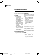
Contents General Information Typical Installation Location and Preparation of Units Unit Installation Connection of Refrigerant Tubing Condensate Drain Piping Electrical Installation Remote Control Installation Typical Wiring Diagram Dimensional Data Notes MS-SVN015-EN 2 4 5 6 7 9 10 11 12 16 18 3 MS-SVN015-EN.
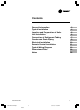
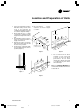
Typical Installation Return air grille contains air filter Supply air grille Adjustable louvers direct air Ceiling mounted Indoor unit Refrigerant tubing/wiring Supply air grille Adjustable louvers direct air Outdoor unit Drain Return air grille contains air filter Low wall mounted Floor mounted Note: For models MCX 042, MCX 048, MCX 060 there are only two styles of installation: under ceiling and low wall 4 MS-SVN015-EN MS-SVN015-EN.
Location and Preparation of Units 1. Select an appropriate position that allows every corners of the room to be uniformly air conditioned and where it is easy to route the refrigerant tubing. 2. Ensure that the floor or ceiling construction is sufficient to fully support the weight of the indoor unit. 3. Consideration must be given to assure an unobstructed flow of supply and return air. 4. Refrigerant tubes between indoor and outdoor units should be as short as possible. 5.
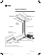
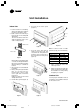
Unit Installation 6. Unscrew at the return grille (Figure 7). Indoor Unit A 1. Select a location to route tubing, wiring and drain pipe between the indoor and outdoor units. 2. Make a hole in the wall using a key hole saw or hole-cutting drill attachment. The hole should be made at a slight downward slant to the outdoor side (Figure 5). 8.5"(215) 0.83"(21) B 0.83"(21) Outdoor side Figure 10 Figure 7 7.
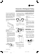
Connection of Refrigerant Tubing The indoor unit refrigerant line connections are flared both 50 Hz and 60 Hz. Installation brazing, leak testing, and evacuation of refrigerant lines are covered in the Installer Manual, packaged with the outdoor unit. Read the instructions before installing the refrigerant lines. When reaming, hold the tube end downward and be sure that no copper scraps fall into the tube. 3. Remove the flare nut from the unit and be sure to mount it on the copper tube.
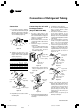
Connection of Refrigerant Tubing Connection Connecting the unit with brazing procedure (Only for MCX 042-060) 9. For proper connection, align the union tube and flare tube straight with each other, then screw in the flare nut lightly at first to obtain a smooth match (Figure 17). Union 1. Cut the copper tube to the required length with a tube cutter. It is recommended to cut approx. 20-30 cm. longer than the tube length you estimate. 2.
Condensate Drain Piping - The drain hose should run straight down the wall to a level where the runoff will not stain the wall. - There should be no traps. Avoid putting the end of the hose in water. - To conveniently drain the system, the drain hose must slant downward, with a slope of at least 1 : 50 to prevent leakage. Figure 23 shows the unit in the floor mounted position.
Electrical Installation All wiring and grounding must comply with local electrical codes. 1. Wiring Important Safeguards: - Check the unit nameplate for electrical rating. Be sure wiring is done according to local codes and wiring diagram. - Use a separate power line with circuit breaker for each air conditioning unit. - Connect electrical ground to all units. - Wiring should not touch refrigerant tubing, compressor, motors or moving parts.
Remote Control Installation Locate and attach the wireless remote control and wired control as follows: 1. Do not place the control and the remote control near heat sources or expose to the direct rays of the sun. 2. Do not expose the control to the indoor unit’s supply air stream. 3. Do not place in a confined space. 4. Attach the remote control holder as shown in Figure 25, 26. 90.0 61.0 14.5 90.0 45.0 14.5 ECON 45.0 4.
Typical Wiring Diagram MCX512-536GB (50 Hz) MCX512-536G1 (60 Hz) INDOOR UNIT, COOLING ONLY WITH CONTROL TYPE “R”, 4 SPEED 1. FREEZE SENSOR LOCATED ON EVAPORATOR COIL 2.
Typical Wiring Diagram MCX042-060GB (50 Hz) MCX042-060G1 (60 Hz) INDOOR UNIT, COOLING ONLY WITH CONTROL TYPE “R”, 3 SPEED 1. FREEZE SENSOR LOCATED ON EVAPORATOR COIL 2.
Typical Wiring Diagram MCX512-536GB (50 Hz) MCX512-536G1 (60 Hz) INDOOR UNIT, COOLING ONLY WITH CONTROL TYPE “W”, 4 SPEED 1. FREEZE SENSOR LOCATED ON EVAPORATOR COIL 2.
Typical Wiring Diagram MCX042-060GB (50 Hz) MCX042-060G1 (60 Hz) INDOOR UNIT, COOLING ONLY WITH CONTROL TYPE “W”, 3 SPEED 1. FREEZE SENSOR LOCATED ON EVAPORATOR COIL 2.
Dimensional Data OUTLINE DIMENSIONS MCX512-536GB (EXPORT 50 Hz) MCX512-536G1 (EXPORT 60 Hz) DIMENSIONAL DATA CONN. SIZES A TYPE B C MODEL LIQUID SUCTION CONNECTIONS. MCX512GB/G1 MCX518GB/G1 1/4 (6.4) 1/2 (12.7) FLARED 42.28 (1074.0) MCX524GB/G1 3/8 (9.5) 5/8 (15.9) FLARED 51.13 MCX530GB/G1 3/8 (9.5) 5/8 (15.9) FLARED MCX536GB/G1 3/8 (9.5) 3/4 (19.0) FLARED NOTE IN. (MM.) IN. (MM.) EACH 34.61 (879.0) 4 (1324.0) 44.45 (1129.0) 4 61.97 (1574.0) 54.29 (1379.0) 6 61.
Dimensional Data OUTLINE DIMENSIONS MCX042-060GB (EXPORT 50 Hz) MCX042-060G1 (EXPORT 60 Hz) DIMENSIONAL DATA CONN. SIZES TYPE A B C D MODEL LIQUID SUCTION CONNECTIONS. MCX042GB/G1 MCX048GB/G1 3/8 (9.5) 3/8 (9.5) 7/8 (22.2) 1-1/8 (28.6) BRAZED BRAZED 71.81 (1824.0) 64.13 (1629.0) 8 15.76 (400) MCX060GB/G1 3/8 (9.5) 1-1/8 (28.6) BRAZED 81.65 (2074.0) 73.98 (1879.0) 8 23.64 (600) NOTE IN. (MM.) 1) DIMENSIONS : MILIMETERS [INCHES] IN. (MM.) EACH IN. (MM.) 25.4 MM.
Notes 18 MS-SVN015-EN MS-SVN015-EN.
Notes MS-SVN015-EN 19 MS-SVN015-EN.
Trane A business of American Standard Companies www.trane.com For more information, contact your local district office MS-SVN015-EN.p65 Literature Order Number: MS-SVN015-EN Date: Jul 2007 Supersedes: Oct 2002 Stocking Location: Bangkok, Thailand Trane has a policy of continuous product and product data improvement and reserves the right to change design and specific ations without notice.