Installation, Owner, and Diagnostic Manual IntelliPak® Commercial Self-Contained Modular Series, 20-35 Ton Models “BO” and later Design Sequence SCWG -020, -025, -030, -035 SIWG -020, -025, -030, -035 SCRG -020, -025, -032 SIRG -020, -025, -032 July 2000 SCXG-SVX01B-EN
General Information About This Manual Literature Change History Use this manual for commercial selfcontained models SCWG, SIWG, SCRG, and SIRG. This is the original issue of this manual. It provides specific installation, owner maintenance, and diagnostic troubleshooting instructions for “BO” and later design sequences. The “BO” design sequence includes the VFD option change from Square D Altivar 66 to Altivar 58. For information on previous design sequences, contact your local Trane representative.
Contents Cross reference to related publications/information: IntelliPak® Self-Contained Programming Guide, PKG-SVP01B-EN Remote Air-Cool-Condenser Installation, Owner, and Diagnostic Manual, CXRCSVX01A-EN Installation General Information Pre-installation Considerations Dimensions/Weights Mechanical Requirements Electrical Requirements Pre-Startup Requirements Programming Startup Owner General Information Sequence of Operation Maintenance Diagnostic Troubleshooting Troubleshooting Diagnostics SCXG-SVX0
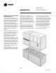
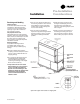
Installation Modular Series Self-Contained Unit Components Commercial self contained units are complete HVAC systems used in floor-byfloor applications. Units are easy to install because they feature a single point power connection, factory installed and tested controls, single water point connection, factory installed options, and an internally trapped drain connection. Modular self-contained units can ship as split-apart units for installation ease.
Installation Control Options Units can have either a thermostat control or IntelliPak® UCM control network. IntelliPak® Unit Controls Standard controls supplied with the IntelliPak® unit include the human interface (HI) panel with unit control module (UCM), hi/lo inlet air temperature sensor, and frost protection. All setup parameters are preset from the factory. Human Interface Panel The HI is unit mounted and accessible without opening the unit’s front panel.
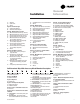
Installation General Information Model Number Description Each self-contained unit has a multiple character model number unique to that unit.To determine a unit’s specific options, reference the model number on the unit nameplate using the model number explanation below.
General Information Installation F = B and C G = A, B and C 0 = None H = Ventilation For 2 Pos. Cntrl Interface 0 = None Digit 26 - Drain Pan Type A = Galvanized Sloped B = Stainless Steel Sloped Digit 27 - Waterside Economizer A = Mechanical Clean Full Cap. (4-row) B = Mechanical Clean Low Cap. (2-row) C = Chemical Clean Full Cap. (4-row) D = Chemical Clean Low Cap.
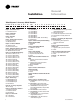
Installation General Information “After-Shipment” Accessory Model Number S C W F N 20 4 2 AO A B 2 10 065 B A 1 0 1 0 A A C F A 1 1 0 T 2 0 1 2 3 4 5 6 7 8 9 10 11 12 13 14 15 16 17 18 19 20 21 22 23 24 25 26 27 28 29 30 31 32 33 34 35 36 Digit 1 - Parts/Accessories P = Parts/Accessories Digit 2 - Unit Model S= Self-Contained Digit 3 - Shipment A = After Unit Digit 4 - Development Sequence F = Signature Series G = Modular Series Digit 5 - Condenser Medium W = Water Cooled R = Remote Air Cooled D
Receiving and Handling Shipping Package Commercial self-contained units ship assembled on skids with protective coverings over the coil and discharge openings. Figure I-PC-1 illustrates a typical shipping package. Ship-Separate Accessories Field-installed sensors ship separately inside the unit’s main control panel. Extra filters, sheaves, and belts ship in the unit’s fan motor section. Condenser plugs, spring isolators, and isopads ship in the unit’s bottom left side.
Installation Installation Preparation Before installing the unit, perform the following procedures to ensure proper unit operation. 1. Verify the floor or foundation is level. Shim or repair as necessary. To ensure proper unit operation, install the unit level (zero tolerance) in both horizontal axis. Failure to level the unit properly can result in condensate management problems, such as standing water inside the unit.
Pre-Installation Considerations Installation Service Access See Figure I-PC-4 and Table I-PC-1 for recommended service and code clearances. Access to thermostat unit controls is through a hinged access panel door on the front, lower left of the unit’s compressor section. IntelliPak® unit control access is through a panel on the middle right of the fan section. The panel is secured with an automatic latch and quick-acting fasteners, which require a screwdriver to open.
Pre-Installation Considerations Installation Rigging and Unit Handling Before lifting the unit or modular component, determine the approximate center of gravity for lifting safety. See Figure I-PC-5 for assembled modular units and Figure I -PC-6 for split-apart units. The center of gravity may vary slightly within the gravity block depending on unit options. ! WARNING Ensure lifting equipment capacity exceeds unit weight by an adequate safety factor to prevent injury, death, or unit damage.
Installation Pre-Installation Considerations Rigging and Handling Unit Shipping 1. Position rigging sling under wood shipping skid. 2. Use spreader bars to avoid unit damage. 3. When using a forklift, exercise caution to prevent unit damage. 4. Use the standard fork length to lift one end and drag or pull unit while skidding the opposite end. 5. The unit center of gravity will fall within center of gravity block at various locations depending on unit options. 6. Use hooks to lift fan section only.
Installation Split-Apart Unit Assembly 1. Ensure the tagging information on the fan section nameplate matches that on the compressor nameplate. 2. Remove the connector brackets holding the the sheet metal shipping cover on compressor section. Retain brackets and screws. 3. Remove shipping cover from the compressor section and verify the shipwith packge contains: • suction and discharge line couplings • insulation • sheet metal screws 4.
Installation Pre-Installation Considerations Figure I-PC-9 How to assemble the split apart modular unit. Figure I-PC-10 Modular unit panel description and internal connections.
Installation Pre-Installation Considerations Skid Removal The unit ships on skids to provide forklift locations from the front or rear.The skid allows easy maneuverability of the unit during storage and transportation. Remove the skids before placing the unit in its permanent location. Remove the skids using a forklift or jack. Lift one end of the unit off of the skids. See Figure I-PC-5 and I-PC-6 on page 12 for unit gravity block location.
Dimensions and Weights Installation SCWG/SIWG Unit — English - (inches) ON PAGE 21 ON PAGE 20 ON PAGE 21 ON PAGE 21 ON PAGE 21 SCXG-SVX01B-EN 17
Dimensions and Weights Installation SCWG/SIWG Unit — Metric- (mm) ON PAGE 21 ON PAGE 21 ON PAGE 21 ON PAGE 21 ON PAGE 21 18 SCXG-SVX01B-EN
Dimensions and Weights Installation SCRG/SIRG Unit — English - (inches) ON PAGE 21 ON PAGE 21 ON PAGE 21 SCXG-SVX01B-EN 19
Dimensions and Weights Installation SCRG/SIRG Unit — Metric - (mm) ON PAGE 21 ON PAGE 21 ON PAGE 21 20 SCXG-SVX01B-EN
Dimensions and Weights Installation SCRG/SIRG/SCWG/SIWG Detail “A” Electrical Connections — English - (inches) SCRG/SIRG/SCWG/SIWG Detail “A” Electrical Connections — Metric - (mm) Detail “B” Discharge Options — English - (inches) and Metric (mm) Unit Dimensions - English, (inches) UnitTons SCWG/SCRG 20 SCWG/SCRG 25 SCWG 30 - 35/SCRG 32 A 20 19 1/4 18 B 10 3/4 12 1/4 14 5/8 C 58 1/2 57 5/8 56 1/2 D 5 1/8 5 1/8 5 1/8 E 13 1/4 13 1/4 13 1/4 F 11 1/2 11 1/2 11 1/2 B 508 489 457 C 1486 1464 1435 D
Dimensions and Weights Installation Hot Water Coil Hot Water Coil Dimensions - English - (inches) Unit Ton 20 - 35 A 37 1/4 B 53 3/4 C 16 5/8 D 73 1/2 E 14 7/8 F 16 1/4 G 43 1/4 H 5 5/8 J 73/4 D 1867 E 378 F 413 G 1099 H 143 J 187 Hot Water Coil Dimensions - Metric (mm) Unit Ton 20 - 35 22 A 946 B 1365 C 422 SCXG-SVX01B-EN
Dimensions and Weights Installation Steam Coil Steam Coil Dimensions - English - (inches) Unit Ton 20 - 35 A 37 1/4 B 53 3/4 C 16 5/8 D 73 1/2 E 10 7/8 K 22 1/2 L 3 3/8 M 15 7/8 N 1 P 41 Q 9 3/8 R 4 3/8 C 422 D 1867 E 276 K 572 L 86 M 403 N 25 P 1041 Q 238 R 111 Steam Coil Dimensions - Metric (mm) Unit Ton 20 - 35 SCXG-SVX01B-EN A 946 B 1365 23
Installation Dimensions and Weights Electric Heat Coil 24 SCXG-SVX01B-EN
Installation Dimensions and Weights Waterside Economizer SCXG-SVX01B-EN 25
Dimensions and Weights Installation Airside Economizer Dimensions - English - (inches) Unit Size SCWG/SIWG 20, 25 SCRG/SIRG 20 SCWG/SIWG 30, 35 SCRG/SIRG 25, 32 A 36 B 65 5/8 C 37 D 74 1/4 E 6 1/8 F (1) 56 1/2 F (2) 49 3/4 G (1) 23 1/4 G (2) 20 1/2 H (1) 5 5/8 H (2) 7 J 20 1/2 K 17 1/8 L 17 M 49 3/4 36 65 5/8 37 74 1/4 6 1/8 61 3/8 62 3/4 28 1/8 20 1/2 3 1/4 7 20 1/2 17 1/8 5 1/2 62 3/4 Airside Economizer Dimensions - Metric (mm) Unit Size SCWG/SIWG 20, 25 SCRG/SIRG 20 SCWG/
Dimensions and Weights Detail “A” Detail “B” (Factory provided for field installation) SCXG-SVX01B-EN 27
Dimensions and Weights Installation Variable Frequency Drive Variable Frequency Drive Dimensions - English - (inches) Motor HP 7.5 7.
Installation Dimensions and Weights Variable Frequency Drive with Bypass SCXG-SVX01B-EN 29
Dimensions and Weights Installation Variable Frequency Drive With Bypass Dimensions - English - (inches) Motor HP 7.5 7.
Installation Dimensions and Weights Flexible Horizontal Discharge Plenum Flexible Horizontal Discharge Plenum Dimensions - English - (inches) 20-35Tons Low Height Standard Height A 35 35 B 17 1/4 25 1/4 C 86 1/2 86 1/2 Flexible Horizontal Discharge Plenum Dimensions - Metric (mm) 20-35Tons Low Height Standard Height SCXG-SVX01B-EN A 889 889 B 438 641 C 2197 2197 31
Dimensions and Weights Installation Table I-DW-1. Unit Weights, English - SCWG/SCRG/SIWG/SIRG Unit Base Airside 2-Row Waterside 4-Row Waterside Heating Size Economizer lbs. 273 273 273 273 Economizer lbs. 488 488 488 488 Economizer lbs. 584 584 584 584 Coil Box lbs. 460 460 460 460 273 273 273 488 488 488 584 584 584 460 460 460 SCWG/SIWG 20 25 30 35 Weight lbs. 2620 2730 2864 3000 SCRG/SIRG 20 25 32 2344 2479 2614 Notes: 1.
Installation Duct Connections ! WARNING Disconnect electrical power source before servicing the unit. Failure to do so may result in injury or death from electrical shock or entanglement in moving parts. Return air enters the rear of the unit and conditioned supply air discharges through the top. Attach supply air ductwork directly to the unit’s top panel, around the fan discharge opening. A duct collar is not provided. Mechanical Requirements unit due to increased noise and excessive static losses.
Water Piping Note: To prevent water damage, install all piping drain and vent plugs. Condenser Connections Condenser water piping knockouts are in the lower left end panel. If necessary, remove insulation to gain access. All field installed piping must conform to applicable local, state, and federal codes. To complete condenser water connections follow the procedure below. Note: Four condenser waterline drain plugs ship in a bag in the unit’s left end.
Installation General Waterside Recommendations: Cooling Towers Cooling tower control affects the unit cycle rates. Condenser water temperature swings from 10-15 degrees F may cause excessive compressor, water valve, and unit cycling. Be sure to set the tower controls to minimize compressor/unit cycling. Waterside Piping Arrangements Install a condenser water pump between the cooling tower (either open or closed) and the self-contained unit.
Installation Refrigerant Piping (Air-Cooled Units Only) The maximum line pressure design of each refrigerant circuit is 3 psig. Include the following items when designing refrigerant piping: oil traps, dual risers, oil return, etc. Refer to the Trane Reciprocating Refrigeration Manual for proper line sizing and layout. See the “Start Up” section on page 74 of this manual for instructions on refrigerant evacuation, charging, and superheat measurement.
Installation Unit Wiring Diagrams Specific unit wiring diagrams are provided on the inside of the control panel door. Use these diagrams for connections or trouble analysis. Supply Power Wiring It is the installer’s responsibility to provide power supply wiring to the unit terminal block or the non-fused disconnect switch option. Wiring should conform to NEC and all applicable code requirements. Bring supply wiring through the knockout in the lower left side of the unit control panel.
Electrical Requirements Installation Selection Procedures RLA = Rated Load Amps Compressor LRA = Locked Rotor Amps Fan Motor LRA = Locked Rotor Amps, N.E.C. Table 430 - 150 FLA = Full Load Amps, N.E.C. Table 430 - 150 Voltage utilization range is ±10 percent Determination of minimum circuit ampacity (MCA). MCA = 1.25 x largest motor amps/VFD amps (FLA or RLA) + the sum of the remaining motor amps. Determination of maximum fuse size (MFS) and maximum circuit breaker size (MCB). MFS and MCB = 2.
Installation Pre-Startup Requirements Pre-Startup Procedures Before starting up units perform the following procedures to ensure proper unit operation. Unit Protective Covers Remove the shipping protection coverings from the human interface panel (HI) at the control panel, the filter box (or air inlet opening), the discharge air opening, and optional variable frequency drive (VFD). Compressor Isolators Loosen compressor isolator mounting bolts and remove shipping bracket from beneath the compressor feet.
Installation Note: The compressors and fan assembly are internally isolated. Therefore, external isolation devices (spring mounting isolators) are at the discretion of a vibration specialist consulted by the building or HVAC system designer. In general, the Trane Company does not recommend double-isolation. Unit Vibration Isolator Option Vibration isolation is not necessary for the unit since the factory internally isolates the fan and compressors, thus creating double isolation.
Pre-Startup Requirements Installation Plenum Before installing the plenum attach the insulation strip that ships with the plenum. See Figure I-PR-4 for proper insulation location. Align the plenum front with the control panel side of the unit. Using the strips and screws provided, secure the plenum to the unit. Treat field-cut holes to prevent fiberglass from entering the airstream. Note: Plenum insulation must be applied properly to prevent air bypass around the plenum. See Figure I-PR-4.
Installation Waterside Economizer Installation Procedure 1. Loosen and pull all end devices that go through the bushing or the filter rack (upper right corner of rack). 2. Remove the filter rack from the back of the unit by removing the 1/4” hex head screws from the top and bottom of the filter rack assembly.The filter rack assembly will hang on the unit when the screws are removed. Remove the filter rack by lifting it up off the unit. 3.
Installation Pre-Startup Requirements Waterside Economizer with Left-Hand Factory Piping Components Figure I-PR-7. Waterside economizer with left-hand factory piping tubing assembly Table I-PR-1. Waterside Economizer Ship-Separate Parts List, LH Figure I-PR-6. Detail view of ship-separate tubing assemblies for waterside economizer left-hand piping.
Installation Pre-Startup Requirements Waterside Economizer with Right-Hand Factory Piping Components Table I-PR-2. Waterside Economizer Ship-Separate Parts List, RH Right-Hand 4001 4607 X17110026250 4605 X153301770100 4008 X17170031210 X16120203570 X17150027060 4007 4606 4603 4006 4460-7575 X21080406030 X21040098390 * These items require field assembly. Item A B C D E F G 1 1 5 2 1 1 1 1 1 1 1 1 1 1 14 ft. 10 ft.
Installation Hydronic Coil Installation These instructions are for steam and hot water coil installation. The hydronic coil assembly has a full coil, piping, a modulating temperature control valve, and a disc temperature limit device located in the unit near the fan on the motor frame. Hydronic coils are available with either right or left-hand pipe connections. Piping connections are identical to the unit piping.
Pre-Startup Requirements Installation Electric Heat Installation The electric heat option consists of a single stage heater and is used in IntelliPak units or units with a fieldinstalled thermostat. The electric heater ships separate for field installation and wiring. Available heater kW per unit size is listed inTable I-PR-3. Electric heat can be installed on units with either a vertical or horizontal discharge. However, it cannot be installed on units with plenums.
Installation Variable Frequency Drive Option (VFD) The variable frequency drive (VFD) option can only be used with IntelliPak units. The VFD and VFD w/bypass is available from 7.5 to 25 hp and is a Square D model Altivar 58. All VFDs are pre-configured and run-tested at the factory prior to shipping. The VFD is wall mounted.
Installation Pre-Startup Requirements Airside Economizer Installation Unit Handling 1. Hoist the damper cabinet to the installation location with straps positioned under the skid as shown in Figure I-PR-12. Use spreader bars to prevent unit damage during lifting. 2. With the damper cabinet at its final location (near the unit), remove the screws securing it to the skid from the side flanges. Retain these screws for later use. Unit Preparation 3.
Installation Static Pressure Transducer Installation (VAV units only) Supply air static pressure controls the inlet guide vane and VFD options. A static pressure head assembly ships separate in the control panel for field installation in the supply air duct work.The installer is responsible for providing pneumatic tubing. Transducer Location Place the head assembly in an area of the ductwork that will provide an average and evenly distributed airflow pattern.
Installation Remote Mounted Thermostat Option Mount the thermostat in the largest space occupied by the most people for the best average temperature sensing. The thermostat should be mounted about 5 feet from the floor in contact with freely circulating air, but not with major drafts. Avoid the following areas: • Behind doors or in corners where ther is no free circulation. • Locations where the sun’s rays or infrared radiation from appliances or fireplaces may affect thermostat operation.
Installation Standard with All Units Pre-Startup Requirements Remote Zone Sensor Options Zone sensor options are available and can be ordered with the unit or after the unit ships. Following is a full description of zone sensors and their functions. Installation instructions are on page 53. Instructions for the programmable zone sensor are on page 55. Refer toTable O-GI-2 on page 79 for the zone sensor temperature vs. resistance coefficient curve. Figure I-PR-15.
Installation CV Unit Zone Sensor Option Figure I-PR-18 BAYSENS010 Dual setpoint, manual/automatic changeover sensor with system function lights, Accessory Model Number Digit 6 = F CV and VAV Unit Zone Sensor Options Pre-Startup Requirements BAYSENS010 Description This zone sensor module is for use with cooling/heating constant volume units without night setback. It has four system switch settings (heat, cool, auto, and off), two fan settings (on and auto), and four LED’s.
Installation Zone Sensor Installation All sensor options ship in the main control panel and are field-installed. Programmable option installation procedures are on page 55. Figure I-PR-21. Standard zone sensor, BAYSENS017, ships with all units. Mounting Location Mount the sensor on the wall in an area with good air circulation at an average temperature.
Installation Pre-Startup Requirements Figure I-PR-22. Zone sensor mounting hole locations. Mounting Directly to the Wall Mounting to Junction Box Junction Figure I-PR-23. Typical zone sensor installation.
Programmable Night Setback Zone Sensors Programmable night setback (NSB) zone sensors provide programming and zone temperature sensing for the selfcontained unit. It allows the user to monitor room temperatures and program settings in the space, without having to access the unit control panel. Reference programming instructions for these zone sensors on page 64.
Installation Programmable Night Setback Zone Sensor Installation Mounting Location Mount the sensor on the wall in an area with good air circulation at an average temperature. Choose a location that is easily accessible, and on a wall where the subbase can be mounted about 5 feet (1.5 meters) above the floor.
Installation Time Clock Option The time clock option has a programmable timer that is factory wired to the unoccupied input to provide on/off control. The time clock will not allow the unit to pass through the night setback/ morning warmup mode, except on units with optional night heat/morning warm up, or programmable night setback. See Figure I-PR-30. Figure I-PR-30. Grasslin time clock option.
Pre-Startup Requirements Installation Installing the Remote Human Interface Panel Human Interface (HI) Panel The HI enables the user to communicate necessary unit operating parameters and receive operating status information from within the occupied space. The HI displays top level information in the LCD window, unless the operator initiates other displays, for the various unit functions. It also displays menu readouts in a clear language 2 line, 40 character format.
Mounting the Remote Human Interface (RHI) Panel The installer must provide all mounting hardware such as; hand tools, electrical boxes, conduit, screws, etc. Refer to Figure I-PR-32 on page 60 for the mounting hole and knockout locations. Procedure Follow the procedure below for mounting the remote HI panel on a 4” by 4” electrical junction box. Place the microprocessor in a clean dry location during the enclosure mounting procedures to prevent damage. 1.
Installation Pre-Startup Requirements Figure I-PR-32. Remote HI mounting holes and knockout locations.
Installation Wiring the Remote Human Interface The remote human interface requires 24 VAC + 4 volts power source and a shielded twisted pair communication link between the remote panel and the interprocessor communication bridge (ICPB) module at the self-contained unit. Field wiring for both the low voltage power and the shielded twisted pair must meet the following requirements: Note: To prevent control malfunctions, do not run low voltage wiring (30 volts or less) in conduit with higher voltage circuits.
Installation Pre-Startup Requirements Connecting to Tracer Summit® Communication Wiring IntelliPak® self-contained units operate withTrane building automation software, Tracer Summit® version 10.0.4 or later or any OS2 operating system. Note: Communication link wiring is a shielded, twisted pair of wire and must comply with applicable electrical codes. ! CAUTION Tape the non-insulated end of the shield on shielded wire at the unit.
Installation Pre-Startup Checklist Complete this checklist after installing the unit to verify all recommended installation procedures are complete before unit start-up. This does not replace the detailed instructions in the appropriate sections of this manual. Always read the entire section carefully to become familiar with the procedures. ! WARNING Disconnect electrical power to prevent injury or death from electrical shock. Receiving oInspect unit and components for shipping damage.
Installation Programming Programmable Zone Sensor Option BAYSENS019 Figure I-P-1. BAYSENS019 Keypad and display configuration. BAYSENS019 Keypad and Display Explanation 1. Up and Down Buttons • Increases or decreased programmed temperature settings in program menu. • Shifts to temporary manual override in normal run mode. • Increases or decreases temperature while in temporary override menu. 2. Time Adjust Button Used to set the correct time of day.
Installation Programming BAYSENS020 Figure I-P-2. BAYSENS020 Keypad and display configuration. BAYSENS020 Keypad and Display Explanation 1. Up and Down Buttons • Increases or decreased programmed temperature settings in program menu. • Shifts to temporary manual override in normal run mode. •Increases or decreases temperature while in temporary override menu. • Pressed together, toggles between unoccupied/occupied setting. 2. Time Adjust Button Used to set the correct time of day.
Initial Power-Up Before applying power to your ZSM, and before performing setup and operation procedures, verify that all wiring is correct. See Figures I-P-9 on page 71 and I-P-10 on page 72 for a complete zone sensor icon display description. For BAYSENS020 only: at initial powerup, the ZSM controls to default temperatures of 68 F (19 C) for warmup, and 55 F (13 C) supply air, until the ZSM is programmed or the arrow keys are pressed.
Note: Blank temperature settings may be entered at any of the four daily periods. When a setpoint is left blank and in an occupied condition, the ZSM will default to the last occupied setpoint. When a setpoint is left blank and in an unoccupied condition, the ZSM will default to the last unoccupied setpoint. Temporary Manual Override While in normal run mode, depressing the hold temp button toggles the ZSM to the temporary manual override menu.
Installation Programming Keypad Operation for Temporary Manual Override Menu The keypad has the same function in temporary manual override menu as in all other menus, with a few exceptions: • Depressing the holdtemp or program buttons while in temporary manual override menu will enter settings and begin temporary manual override run mode. See Figure I-P-5.
Installation Option Menu and Keypad Operation The operation menu sets all programmable options built into your ZSM. All options are retained in permanent EEPROM memory. To access the option menu display, simultaneously depress and hold the mode button and program button for four seconds. See Figure I-P-8. The example in Figure I-P-8 shows option 15 displayed and indicates the initial timer setting in the temporary override run mode. The option value shown is in hours, and value selected is five hours.
Installation Programming Note: On both programmable zone sensor options, changing either option 9 or 10 will erase the current program. To avoid reprogramming, set options 9 and 10 before programming. Table I-P-2. Zone Sensor BAYSENS020 Option Menu Settings.
Installation Programming Figure I-P-9. BAYSENS019 complete icon display. Icon Descriptions BAYSENS019 Icon Descriptions Refer to Figure I-P-9 for a pictorial view of the written descriptions below. 1. The four periods of the day used only during programming mode. 2. The seven days of the week used during programming and in normal mode to display the day (not current in Program Menu). 3. Four digits used to display the time of day in normal run mode.
Installation Programming Figure I-P-10. BAYSENS020 complete icon display. BAYSEN020 Icon Descriptions Refer to Figure I-P-10 for a pictorial view of the written descriptions below. 1. The four periods of the day used only during programming mode. 2. The seven days of the week used during programming and in normal run mode. 3. Four digits used to display the time of day in normal run mode. Also used in Programming Mode, override timer setting menu, and options menu. 4.
Programming the Time Clock Option Setting the Time Important: Depress reset key before beginning to set time and program. 1. Select military (24:00 hr.) or AM/PM (12:00 hr.) time mode by depressing and holding the “h” key while pressing “+ 1h” key to toggle between military and AM/PM. (AM appears in the display when in AM/PM mode.) 2. Press and hold down “¹” key. 3. If setting the time when daylight savings time is in effect, press “+ 1h” key once (+ 1h will appear in display). 4. Set hour with “h” key.
Unit Startup Procedures 1. Check all electrical connections for tightness. 2. For water-cooled units: gain access to the liquid line service valves in the unit’s left lower section. Note: Verify the liquid line service valve is open at unit start-up. Each compressor suction line contains a low pressure sensor that will shut the compressor down in low pressure situations. See Table O-SO2 on page 97. ! CAUTION Never manually or automatically pump down below 7 psig.
Installation Startup Startup Log Complete this log at unit start-up.
Installation Startup Water Cooled Units: Circuit A: Entering Water Temperature - F: __________ Leaving Water Temperature - F: __________ Entering Water Pressure - psig: __________ Leaving Water Pressure - psig: __________ Circuit B: Enter Water Temperature - F: __________ Leaving Water Temperature - F: __________ Entering Water Pressure - psig: __________ Leaving Water Pressure - psig: __________ Circuit C: Entering Water Temperature - F: __________ Leaving Water Temperature - F: __________ Ent
Owner General Information Points List ECEM Module: RTM Module: Analog inputs • Return air temperature • Return air humidity Binary inputs • Emergency stop • External auto/stop • Unoccupied/occupied • Dirty filter • VAV changeover with hydronic heat Binary outputs • VAV box drive max (VAV units only) • CV unoccupied mode indicator (CV units only) • Alarm • Fan run request • Water pump request (water-cooled only) Analog input • Airside economizer damper minimum position Analog output • Outside air dampe
Owner Unit Control Components ® The Modular Series IntelliPak selfcontained unit is controlled by a microelectronic control system that consists of a network of modules. These modules are referred to as unit control modules (UCM). In this manual, the acronym UCM refers to the entire control system network. These modules perform specific unit functions using proportional/integral control algorithms. They are mounted in the unit control panel and are factory wired to their respective internal components.
General Information Owner Occupied/Unoccupied Contacts To provide night setback control if a remote panel with night setback was not ordered, install a field-supplied contact. This binary input provides the building’s occupied/unoccupied status to the RTM. It can be initiated by a time clock, or a building automation system control output. The relay’s contacts must be rated for 12 ma @ 24 VDC minimum.
Owner Compressor Module (SCM and MCM - Standard on All Units Waterside Module - Standard on All Water-Cooled Units The compressor module, (single circuit and multiple circuit) energizes the appropriate compressors and condenser fans upon receiving a request for mechanical cooling. It monitors the compressor operation through feedback information it receives from various protection devices. The waterside module (WSM) controls all water valves based on unit configuration.
Owner General Information • VO relay – energized • Exhaust fan (field-installed) - on • Exhaust damper (field-installed) - open application are; switch 1 “off,” 2 “on,” and 3 “off.” Ventilation Control Module (VCM) - Available only with Traq™ Damper Option PURGE sequence “D” This sequence could be used for purging the air out of a building before coming out of unoccupied mode of operation on VAV units. Also, it can be used to purge smoke or stale air.
Owner Generic Building Automation System Module Option The generic building automation system module (GBAS) provides broad control capabilities for building automation systems other than Trane’s Tracer® system.
General Information Owner Table O-GI-6. GBAS Analog Input Setpoints Control Parameter Signal Range Setpoint Range Occupied Zone Cooling Setpoint 0.5 to 4.5 vdc 50 to 90 F (CV units only) Unoccupied Zone Cooling Setpoint 0.5 to 4.5 vdc 50 to 90 F (CV and VAV) Occupied Zone Heating Setpoint 0.5 to 4.5 vdc 50 to 90 F (CV units only) Unoccupied Zone Heating Setpoint 0.5 to 4.5 vdc 50 to 90 F (CV and VAV) Supply Air Cooling Setpoint 0.5 to 4.
General Information Owner Waterside Components Waterside components consist of water piping, water valves, water flow switch option, water cooled condensers (SXWF only), and the economizer option. Water Purge This user-definable feature allows the user to select a purge schedule to automatically circulate water through the economizer and condensers periodically during non-operational times. This allows fresh chemicals to circulate in waterside heat exchangers.
General Information Owner condenser bypass valve closes, and vice versa. Full water flow is always maintained through the condensers. Both valves will close in the event of a power failure. See Figures O-GI-3 and O-GI-5. • Variable Water Flow Two-way modulating control shutoff valves are wired, controlled, and installed in the unit. One valve is located in the economizer’s water inlet, and the other is in the condenser bypass water inlet.
Unit Airside Components The unit’s air delivery system consists of condensers, dampers, enthalpy switch option, airside economizer option, filters, low ambient sensors, and factory mounted single or double wall plenums. Supply Air Fan The unit has a single supply fan that runs at a constant speed. However, the fan may have the IGV or VFD option that modulates airflow based on supply air temperature control. Pressing the stop key on the HI will turn the supply fan off.
Owner mode at the HI panel. When in bypass mode, VAV boxes need to be fully open. The self-contained unit will control heating and cooling functions to maintain setpoint from a user-defined zone sensor. Supply air static pressure limit is active in this mode. and permits the outdoor air damper to open only to the minimum position. For more detailed information on VFD operation, reference the Square D VFD technical manual that ships with the unit.
General Information Owner Standard Two-Position Damper Interface Units with the two-position damper interface are provided with a 0-10 VDC control output suitable for controlling a field-provided modulating actuator. In occupied mode, the output drives to the maximum position.
Owner Input Devices and System Functions all compressor operation for that circuit, and initiates a manual reset diagnostic. Following are basic input device and system function descriptions used within the UCM network on IntelliPak® selfcontained units. Refer to the unit wiring diagrams for specific connections. Low Pressure Control Low pressure (LP) control uses a binary input device. LP cutouts are mounted on the suction lines near the compressors.
condenser water temperature exceeds 58 F. Low Ambient Control (Air-Cooled Units Only) The low ambient modulating output on the compressor module is functional on all units with or without the low ambient option. When the compressor module stages up to it's highest stage (stage 2 or 3 depending on unit size), the modulating output is 100% (10 VDC).
Owner Sequence of Operation Control Sequences of Operation on the unoccupied input for more than five seconds. temperature is below the MWU setpoint, the unit enters the MWU mode.
Owner Timed Override Activation - ICS™ This function is operational whenever the unit’s RTM module is used as the zone temperature sensor source, which can be set at the HI panel. When this function is initiated by the push of the override button on the zone sensor, the unit will switch to the occupied mode. Unit operation (occupied mode) during timed override is terminated by a signal from Tracer®.
Owner Occupied Sequence Of Operation All setpoints can be adjusted using the HI panel. Also, cooling/heating setpoints can be adjusted in the zone, if using one of the zone sensor options (BAYSENS020, BAYSENS021, BAYSENS008, BAYSENS010, BAYSENS019, or BAYSENS014). For a complete list of unit setpoint default values and ranges, see the IntelliPak® Self-Contained Programming Guide, PKG-SVP01B-EN.
Owner control setting, only mechanical cooling will function and outside air dampers will remain at their minimum position. Mechanical Cooling If the zone temperature cannot be maintained within the setpoint deadband using the economizer option or if there is no economizer, the RTM sends a cooling request to the MCM. The compressor module checks the compressor protection circuit before closing stage one.
Sequence of Operation Owner Compressors Units use two sizes of hermetic scroll compressors, 10 and 15 hp, and can use from two to four compressors. When viewing the front of the unit, compressors are identified A through B from left to right.The second compressor from the left, or B compressor, is always the first to come on, unless locked out for a malfunction or shut off on frost protection.
Sequence of Operation Owner Compressor Safety Devices The compressors have motor temperature cutout switches in the motor windings. These switches are provided to take the compressors off line during high motor winding temperature conditions. If a compressor low pressure cutout opens during compressor start-up, the UCM will not shut the compressor off during the first two to three minutes after start-up. This prevents possible nuisance trips during low ambient start conditions. See Table O-SO-2.
Owner Sequence of Operation band according to the desired unit performance. Increasing the control band reduces the equipment cycle rate and increases the maximum potential supply air temperature deviation from setpoint. Conversely, decreasing the control band reduces the maximum potential temperature deviation, but increases the compressor cycle rate.
Maintenance Procedures Air Filters Filter access doors are on the same side of the unit as the water piping connections. To replace throwaway filters, remove the dirty elements and install new filters with the filter’s directional arrows pointing toward the fan. Verify that no air bypasses the filters. All unit sizes require four 16 x 25 x 2 inch (508 x 635 x 51 mm) and four 20 x 25 x 2 inch (508 x 635 x 51 mm) filters.
Owner Maintenance Supply Fan each sheave and pull it tight for a center line. See Figure O-M-2 on page 100 for recommended torques. 4. Once the sheaves are properly aligned, tighten sheave set screws to proper torque. 5. Check belt tension. Refer to the “Measuring Belt Tension” section on page 100. 6. If required, adjust belt to the minimum recommended tension. Refer to “Adjusting Belt Tension” section on page 100. 7. Retighten bearing set screws to the proper torques after aligning the sheaves. 8.
Fan Bearings The opposite drive end bearing is a special bearing with close tolerance fit of balls and races. Replace this bearing with the same part number as the original bearing. Fan Belt Tension Note: Check fan belt tension at least twice during the first days of new belt operation since there is a rapid decrease in tension until belts are run-in. Proper belt tension is necessary to endure maximum bearing and drive component life and is based on fan brake horsepower requirements.
Owner Maintenance Figure O-M-5. Fan assembly. Figure O-M-6 . Fan motor adjustment points.
Owner Maintenance Refrigerant System Follow specific manufacturer’s guidelines for conversion of existing systems. •To assist in reducing power generation emissions, always attempt to improve equipment performance with improved maintenance and operations that will help conserve energy resources. Special Note on Refrigerant Emissions Follow the Trane recommended procedures on operation, maintenance, and service to ensure refrigerant conservation and emission reduction.
Owner nitrogen into the system to raise the pressure to 100 psig. 2. Use a halogen leak detector, halide torch, or soap bubbles to check for leaks. Check interconnecting piping joints, the evaporator coil connections, and all accessory connections. 3. If a leak is detected, release the test pressure, break the connections and reassemble it as a new joint, using proper brazing techniques. 4. If no leak is detected, use nitrogen to increase the test pressure to 150 psig and repeat the leak test.
Owner ! WARNING Maintenance ! WARNING Do not exceed 200 psig when leak testing the system. Damage to the unit could result, or an explosion may occur causing injury or death. In the event of required system repair, leak test the liquid line, evaporator coil, and suction line at pressures dictated by local codes, using the following guidelines. 1. Charge enough refrigerant and dry weight. Use an accurate scale or charging cylinder to determine the exact weight of the refrigerant entering the system.
Owner Maintenance Figure O-M-7. Typical water-cooled (SXWG) compressor section components.
Owner Maintenance Inlet Guide Vanes On occasion, the inlet guide vane actuator or inlet guide vanes may need to be removed. For proper adjustment of inlet guide vanes and/or actuator, see Figure O-M-8. Perform the following procedure every six months for proper inlet guide vane operation: 1. Spray all parts of guide vane assembly with WD40. 2. Spray all steel parts of guide vane assembly with ZRC. 3.
Owner Coil Fin and External Cleaning Keep coils clean to maintain maximum performance. For operation at its highest efficiency, clean the refrigerant coil often during periods of high cooling demand or when dirty conditions prevail. Clean the coil a minimum of once per year to prevent dirt buildup in the coil fins, where it may not be visible. Remove large debris from the coils and straighten fins before cleaning. Remove filters before cleaning.
Owner Maintenance Also, a drain plug is at the bottom of the inlet condenser manifold and in the outlet pipe near the unit’s left side. Remove these plugs to drain the condensers. Be sure to open the vent plugs at the top of the condenser inlet and outlet manifold. See Figure O-M-7 on page 105. 2. Remove the condenser’s left side to expose the condenser tubes. 3. Rotate a round brush through the tubes to loosen contaminant. 4.
Owner Maintenance Piping Components clip holds the paddle assembly in the switch body. 3. Remove the wire retainer clip by reaching down past the paddle with a pair of slim nosed pliers and gripping the end of the wire. Pull up on the wire clip and remove it. 4. After removing the wire clip, use the pliers to pull the paddle assembly out of the switch barrel. Clamp the pliers onto the end of the paddle and remove the paddle assembly. It will slide straight out. 5.
Periodic Maintenance Checklists Monthly Checklist The following check list provides the recommended maintenance schedule to keep the unit running efficiently. ! WARNING Disconnect power source and allow all rotating equipment to stop completely before servicing or inspecting the unit. Failure to do so may result in injury or death. 1. Inspect unit air filters. Clean or replace if airflow is blocked or if filters are dirty. 2. Inspect coils for excess moisture or icing.
Diagnostic Troubleshooting Troubleshooting System Checks Before proceeding with technical trouble charts or controls checkout, complete the follow system analysis: 1. Measure actual supply voltage at the compressor and an motor terminals with the unit running. Voltage must be within the range listed on the motor nameplate. Phase imbalance must be less than 2.0 percent. 2. Check all wiring and connections to be sure that they are intact, secure and properly routed.
Diagnostic Troubleshooting Diagnostics Diagnostics Refer to the IntelliPak® Self-Contained Programming Guide, PKG-SVP01B-EN, for specific unit programming and troubleshooting information. In particular, reference the “Service Mode Menu” and “Diagnostic Menu” sections in the programming guide. Refer to the following text for general diagnostic and troubleshooting procedures. Common diagnostics and troubleshooting procedures follow below.
Diagnostic Troubleshooting Diagnostics Reset Required: (PAR) An automatic reset occurs after communication has been restored. Emergency Stop Problem: The emergency top input is open. Reason for Diagnostic: An open circuit has occurred on the emergency stop input caused either by a high duct temp tstat trip, or the opening of field-provided contacts, switch, etc. UCM’s Reaction: Off or close requests are issued as appropriate to the following functions; a. Compressor staging/chilled water cooling control b.
Diagnostic Troubleshooting Diagnostics this input (temp < -55 F or temp > 209 F). UCM’s Reaction:The functions that designated the heat module auxillary temperature input as their input are disabled. Reset Required: (PAR) An automatic reset occurs after the heat module auxillary temperature input returns to its allowable range for 10 seconds. Heat Module Comm Failure Problem: The RTM has lost communication with the heat module. Check: Check field/unit wiring between RTM and heat module.
Diagnostic Troubleshooting Diagnostics UCM’s Reaction: The system mode reverts to the default (HI set) system mode. Reset Required: (INFO) An automatic reset occurs after the mode input returns to its allowable range for 10 seconds. N NSB Panel Zone Temperature Sensor Failure Problem: The NSB panel's zone temp sensor input is out of range. (This input is at the NSB panel, not on the unit itself).
Diagnostic Troubleshooting Diagnostics its allowable range continuously for 10 seconds. RTM Aux. Temp. Sensor Failure Problem: The RTM auxillary temperature sensor data is out of range. Check: Sensor resistance should be between 830 ohms (200 F)and 345.7 Kohms (-40 F). If so, check field/unit wiring between sensor and RTM.
Diagnostic Troubleshooting Diagnostics range for 10 continuous seconds, or after a different SA pressure setpoint source is user-defined. Reason for Diagnostic: The unit is reading a signal that is out of range for the supply air temperature input on the RTM (temp. < -55 F or temp > 209 F). Supply Air Temp Cool Setpoint Fail Problem: The active supply air temperature cooling setpoint is out of range.
Diagnostic Troubleshooting Diagnostics Reason for Diagnostic: The TCI has lost communications with Tracer Summit® for > 15 minutes. UCM’s Reaction: All active commands and setpoints provided by Tracer Summit® through the TCI will be cancelled and/or ignored. And where Tracer vSummit® has been designated as the setpoint source, local HI default setpoints are used. Reset Required: (PAR) An automatic reset occurs after communication between Tracer Summit® and the TCI is restored.
Diagnostic Troubleshooting Diagnostics W WSM Communications Fail Problem: The RTM has lost communication with the WSM. Check: Field/unit wiring between RTM and WSM. Reason for Diagnostic: The RTM has lost communication with the WSM.
Index A “After-Shipment” Accessory Model Number 8 Air Filters 98 Air-Cooled Condensers 88 Airside Economizer Installation 48 Airside Economizer Interface 88 Airside Economizer Interface with Comparative Enth 88 Airside Economizer Option 87 Airside Economizers with Traq Damper 87 Ambient Temperature and Humidity Limits 58 Annual Maintenance 110 Auto Changeover 94 Auto Reset S/A Static Pressure Limit 112 B Basic Water Piping 84 BAYSEN020 Icon Descriptions 72 BAYSENS008 Description 50 BAYSENS010 Description 5
Index Sensor Fail 113 Heat Module Comm Failure 114 HI 58, 80 HI Location Recommendations 58 High Duct Static Switch 90 High Duct Temp Thermostat 90 High Duct Temperature Thermostat 86 high duct thermostat can be reset 90 Holdtemp Button 67 Human Interface 58 Human Interface Module 80 Human Interface Panel 5 Hydronic Coil Installation 45 Hydronic Heat 94 I Icon Descriptions 71 ICPB 61 Initial Power-Up 66 Inlet Guide Vane 86 Inlet Guide Vanes 106 Input Devices and System Functions 89 Inspecting and Cleaning
Index Return Air Humidity Sensor Failure 115 Return Air Temp Sensor Failure 115 Return Air Temperature Sensor 90 RHI 58, 80 Rigging and Handling 13 Rigging and Unit Handling 12 RTM Alarm Relay 78 RTM Analog Outputs 78 RTM Aux. Temp.
Index Water Temperature Requirements 35 Water Valves 109 Water-Cooled Condensers 84 Water-Cooled Unit Piping 63 Waterside Components 84 Waterside Economizer Flow Control 84 Waterside Economizer Installation Procedure 42 Waterside Economizer Option 84 Waterside Module 80 Waterside Piping Arrangements 35 Wiring 53 Wiring the Remote Air-cooled CCRC and SCRG 50 SCXG-SVX01B-EN Wiring the Remote Human Interface 61 Wiring the Timeclock 57 WSM 80 WSM Communications Fail 119 WSM Mixed Air Temp Sensor Fail 119 Z Z
TheTrane Company A Division of American Standard Inc. www.trane.com For more information contact your local district office or e-mail us at comfort@trane.com An American Standard Company Literature Order Number SCXG-SVX01B-EN File Number PL-UN-SCXF-SVX01B-EN 700 Supersedes SCXG-SVX01A-EN Stocking Location LaCrosse - Inland SinceTheTrane Company has a policy of continuous product improvement, it reserves the right to change design and specifications without notice.