
Datasheet


Application Note
Created by Traco Electronic AG Arp.
www.tracopower.com
Date: May 22, 2018 / Rev.: 1.0 /
Page 57 / 63
12W, Single and Dual Output
Input Source Impedance
The power module should be connected to a low impedance input source. Highly inductive source impedance can affect the
stability of the power module. Input external L-C filter is recommended to minimize input reflected ripple current. The inductor is
simulated source impedance of 12μH and capacitor is Nippon Chemi-Con KZE series 47μF/100V. The capacitor must as close
as possible to the input terminals of the power module for lower impedance.
Output Over Current Protection
When excessive output currents occur in the system, circuit protection is required on all power supplies. Normally, overload
current is maintained at approximately about 150 percent of rated current for THD 12 output series.
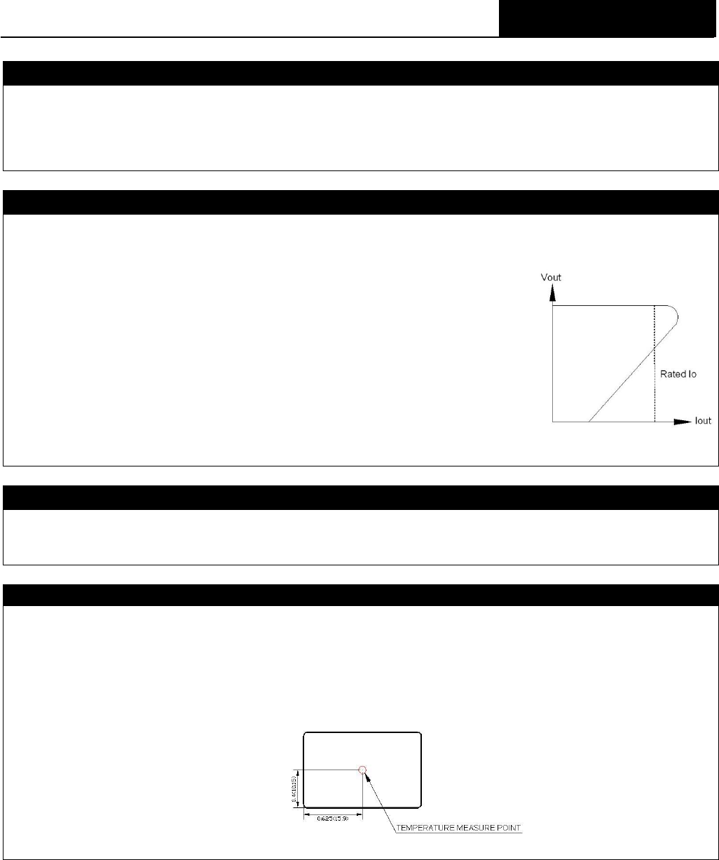
Fold back-mode is a method of operation in a power supply whose purpose is to protect the
power supply from being damaged during an over-current fault condition. It also enables the
power supply to operate normally when the fault is removed.
One of the problems resulting from over current is that excessive heat may be generated in
power devices; especially MOSFET and Schottky diodes and the temperature of those
devices may exceed their specified limits. A protection mechanism has to be used to prevent
those power devices from being damaged.
The operation of fold back is as follows. When the current sense circuit sees an over-current
event, the output voltage of the module will be decreased for low power dissipation and
decrease the heat of the module.
Output Over Voltage Protection
The output over-voltage protection consists of output Zener diode that monitors the voltage on the output terminals. If the
voltage on the output terminals exceeds the over-voltage protection threshold, then the Zener diode clamps the output voltage.
Thermal Consideration
The power module operates in a variety of thermal environments. However, sufficient cooling should be provided to help ensure
reliable operation of the unit. Heat is removed by conduction, convection, and radiation to the surrounding Environment. Proper
cooling can be verified by measuring the point as the figure below. The temperature at this location should not exceed 105°C.
When Operating, adequate cooling must be provided to maintain the test point temperature at or below 105°C. Although the
maximum point Temperature of the power modules is 105°C, you can limit this Temperature to a lower value for extremely high
reliability.
TOP VIEW
Measurement shown in inches and (millimeters)