LOCATION OF HEATER Heaters should be located to provide a blanket of heat over the coldest wall of the room, preferably on a outside wall under a window. CAUTIONS AND WARNING STATEMENTS 1. Wiring procedures and connections should be in accordance with national and local codes having jurisdiction. Note: all baseboards must be grounded in accordance with article 250 of the N.E.C. 2. Do not install baseboard heater below electrical convenience receptacles (outlets). 3.
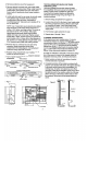
. Remove junction box cover from supply end. 3. Remove desired knockouts and route supply cable through openings using proper fitting. Using means to protect finish, place heater face down with bottom toward wall and positioned where heater location is desired. 4. Locate Walt studs and fine up center of stud with notch along bottom edge of heater. Remove keyhole mounting hole in line with notch. Provisions for mounting repeat at4” intervals to aid in locating center stud.
INSTALLATION INSTRUCTIONS BUILT-IN THERMOSTAT CAUTION: Disconnect supply service to avoid electric shock. All wiring connections must conform to national electric code and local codes having jurisdiction. NOTES: * Do not eliminate or bypass the thermal cutout. Be sure load controlled by the thermostat does not exceed the thermostat nameplate rating. The in-built thermostat accessory can be mounted in either end of baseboard. 1. Remove junction box cover. 2.
INSTALLATION INSTRUCTIONS INBUILT DUPLEX RECEPTACLE CAUTION: Disconnect supply service to baseboard and receptacle to avoid electrical shock. All wiring connections must conform to National Electric Code and Local Codes having jurisdiction. NOTE: The receptacle must be connected to a branch circuit, other than the baseboard heater circuit, having over current protection in accordance with the National Electric Code. 1. The receptacle cover assembly can be mounted in the left or right hand junction box. 2.
INSTALLATION INSTRUCTIONS LOW VOLTAGE RELAY SECTION CAUTION: Disconnect supply service to avoid electrical shock. All wiring connections must conform to the national electric code and local codes having jurisdiction. i. Remove front cover. 2. Remove 1/2" diameter knockout in upper low voltage section, install 1/2" snap bushing (supplied). 3. Remove knockout in lower section for power supply. Remove knockout from exposed end of baseboard for heater wire entry. 4.
INSTALLATION INSTRUCTIONS TRANSFER SWITCH WITH RECEPTACLE SECTION CAUTION: Disconnect supply service to avoid electrical shock. All wiring connections must conform to national electric code and local codes having jurisdiction. 1. Remove front covers from accessory and baseboard. 2. Remove knockout for supply entrance and knockout from exposed end of baseboard for heater wire entry. 3. Attach accessory to wall with heater, insert bushing (supplied) from baseboard junction box. 4.
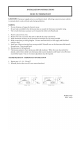
INSTALLATION INSTRUCTIONS BASEBOARD JOINER KIT CAUTION: Disconnect supply service to avoid electric shock. All wiring connections must conform to national electric code and local codes having jurisdiction. .1. Remove junction box covers. 2. Remove large and small knockouts from exposed ends of "baseboards. . "3. Temporally assemble baseboards with machine screw, lock washers, and nut. Insert snap bushing into the 7/8 in. holes. 4. After the baseboards are aligned, finish tightening the machine screw.
INSTALLATION INSTRUCTIONS INSIDE / OUTSIDE CORNER SECTION CAUTION: Disconnect supply service to avoid electrical shock. All wiring connections must conform to national electric code and local codes having jurisdiction. 1. Remove junction box covers from baseboard heaters that are to be joined to the corner section. 2. Remove the top cover from the corner section. 3. Remove small and large knockouts from exposed ends of baseboards to be connected to the corner section. 4.
INSTALLATION INSTRUCTIONS WIRE WAY ADAPTER CAUTION: Disconnect supply service to avoid electrical shock. All wiring must conform to national electric code and all local codes having jurisdiction. 1. Remove junction box covers. 2. Remove bottom knockouts on bottom of junction boxes on heat shield side. Insert snap bushings provided. 3. Using means to protect finish, place baseboard face down.
INSTALLATION INSTRUCTIONS BASEBOARD BLANK SECTION CAUTION: Disconnect supply service to avoid electrical shock. All wiring connections must conform to national electrical codes having jurisdiction. NOTE: The baseboard blank section mounts against the wall similar to the baseboard. When making wiring connection: for wiring single baseboard and the supply is through the blank section or when wiring for continuous parallel connections for multiple baseboard installation, then a wire way adapter must be used.
INSTALLATION INSTRUCTIONS DISCONNECT SWITCH CAUTION: Disconnect supply service to baseboard to avoid electrical shock. All wiring connections must conform to National Electric Code and local codes having jurisdiction. NOTES: *Do not eliminate or bypass the thermal cutout. *Do not exceed the name plate rating. *The in-built accessory can be mounted in either end of baseboard. 1. Remove junction box cover, retain screw. 2. Remove wire nut in junction box (Do not disturb the crimp nut connection). 3.
INSTALLATION INSTRUCTIONS COVER MOUNTED BUILT-IN THERMOSTAT ACCESSORY CAUTION: DISCONNECT SUPPLY SERVICE TQ AVOID ELECTRIC SHOCK. ALL WIRING CONNECTIONS MUST CONFORM TO NATIONAL ELECTRIC CODE AND LOCAL CODES HAVING JURISDICTION. NOTES: Do not eliminate or bypass the thermal cutout. Be sure load controlled by the thermostat does not exceed the thermostat nameplate rating. The built-in thermostat accessory can be mounted in either end of the baseboard.