
User Guide


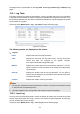


Table Of Contents
- Package Contents
- Chapter 1 About this Guide
- Chapter 2 Introduction
- Chapter 3 Login to the Switch
- Chapter 4 System
- Chapter 5 Switching
- Chapter 6 VLAN
- Chapter 7 Spanning Tree
- Chapter 8 Multicast
- Chapter 9 QoS
- Chapter 10 ACL
- Chapter 11 Network Security
- Chapter 12 SNMP
- Chapter 13 LLDP
- Chapter 14 Cluster
- Chapter 15 Maintenance
- Chapter 16 System Maintenance via FTP
- Appendix A: Specifications
- Appendix B: Configuring the PCs
- Appendix C: 802.1X Client Software
- Appendix D: Glossary

14.4 Application Example for Cluster Function
Network Requirements
Three switches form cluster, one commander switch and two member switches. The administrator
manages all the switches in the cluster via the commander switch.
Port 1 of the commander switch is connecting to the external network, port 2 is connecting to
member switch 1 and port 3 is connecting to member switch 2.
IP pool: 175.128.0.1, Mask: 255.255.255.0.
Network Diagram
Figure 14-19 Network diagram
Configuration Procedure
Configure the member switch
Step Operation Description
1 Enable NDP function on the
switch and for port 1
On Cluster→NDP→NDP Config page, enable NDP
function.
2 Enable NTDP function on the
switch and for port 1
On Cluster→NTDP→NTDP Config page, enable
NTDP function.
Configure the commander switch
Step Operation Description
1 Enable NDP function on the
switch and for ports 1-3
On Cluster→NDP→NDP Config page, enable NDP
function.
2 Enable NTDP function on the
switch and for ports 1-3
On Cluster→NTDP→NTDP Config page, enable
NTDP function.
215