Enterprise Networking Solution User Guide Gigabit Uplink Web Smart Switch TL-SL2210WEB/TL-SL2218WEB TL-SL2428WEB/TL-SL2452WEB
COPYRIGHT & TRADEMARKS Specifications are subject to change without notice. is a registered trademark of TP-LINK TECHNOLOGIES CO., LTD. Other brands and product names are trademarks of their respective holders. No part of the specifications may be reproduced in any form or by any means or used to make any derivative such as translation, transformation, or adaptation without permission from TP-LINK TECHNOLOGIES CO., LTD. Copyright © 2012 TP-LINK TECHNOLOGIES CO., LTD. All rights reserved. http://www.tp-link.
Related Document This User Guide is also available in PDF on our website. To obtain the latest product information, please visit the official website: http://www.tp-link.com About this User Guide This User Guide describes the hardware characteristics, installation methods and the points that should be attended to during installation. This User Guide is structured as follows: Chapter 1 Introduction. This chapter describes the external components of the Switch. Chapter 2 Installation.
Audience This User Guide is for: Network Engineer Network Administrator Conventions Due to the similarity in structure of TL-SL2210WEB/TL-SL2218WEB/TL-SL2428WEB/ TL-SL2452WEB Gigabit Uplink Web Smart Switch series, in this User Guide we take TL-SL2210WEB as an example to illustrate Chapter 2 Installation, Chapter 3 Lightning Protection, Chapter 4 Connection and Chapter 6 WEB Management. This Guide uses the specific formats to highlight special messages.
Contents Chapter 1 Introduction ——————————————— 01 1.1 Product Overview ............................................................................................ 01 1.2 Features ............................................................................................................... 01 1.3 Appearance ........................................................................................................ 02 Chapter 2 Installation ———————————————— 05 2.1 Package Contents .................
5.3.5 5.3.6 5.4 5.4.1 Dynamic Binding...................................................................................... 18 Ping ............................................................................................................... 19 VLAN Setting ..................................................................................................... 19 VLAN Mode ................................................................................................ 19 5.5 Port Trunking ................
Gigabit Uplink Web Smart Switch CCCCCCCCCC Introduction 1111 Product Overview The TL-SL2210WEB/TL-SL2218WEB/TL-SL2428WEB/TL-SL2452WEB Gigabit Uplink Web Smart Switch is compliant with the IEEE802.3 Ethernet protocols. The EIA-standardized framework and smart configuration capacity can provide flexible solutions for variable scale of networks. This switch family is equipped with powerful management interface, via which system, port, network, VLAN, truck and priority can be configured.
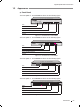
Gigabit Uplink Web Smart Switch 1111 Appearance ■■ Front Panel The front panel of TL-SL2210WEB is shown as the following figure.
Gigabit Uplink Web Smart Switch RESET Press this button for three seconds to reset the software setting back to factory default setting. LEDs LED Power System Link/Act 100Mbps 1000Mbps Status Indication On The Switch is powered on Off The Switch is powered off or power supply is abnormal On The Switch works properly Off The Switch works improperly On A valid link is established on the port Flashing Data is being transmitted or received.
Gigabit Uplink Web Smart Switch ■■ Rear Panel The rear panel of TL-SL2210WEB/TL-SL2218WEB/TL-SL2428WEB/TL-SL2452WEB is shown as the following figure. Power Socket FFFFFFFFFFF Rear Panel Power Socket Connect the female connector of the power cord here, and the male connector to the AC power outlet. Please make sure the voltage of the power supply meets the requirement of the input voltage. Caution: Please use the provided power cord.
Gigabit Uplink Web Smart Switch CCCCCCCCCC Installation 2222 Package Contents Make sure that the package contains the following items. If any of the listed items is damaged or missing, please contact your distributor.
Gigabit Uplink Web Smart Switch Site Requirements ■■ To ensure normal eperation and long service life of the device, please install it in an environment that meets the requirements described in the following subsection.
Gigabit Uplink Web Smart Switch Keep the device far from high-frequency, strong-current devices, such as radio transmitting station. ■■ Use electromagnetic shielding when necessary.
Gigabit Uplink Web Smart Switch 2222 Installation Tools ■■ Phillips screwdriver ■■ ESD-preventive wrist wrap ■■ Cables Note: These tools are not provided with our product. If needed, please self purchase them. 2222 Product Installation ■■ Desktop Installation To install the device on the desktop, please follow the steps: 111Set the device on a flat surface strong enough to support the entire weight of the device with all fittings. 222Remove the adhesive backing papers from the rubber feet.
Gigabit Uplink Web Smart Switch Rack-mounting Bracket Screw R Power TL-SL221 0WEB Link Act System 100M 1 2 3 4 5 6 7 8+2G Link/Act 8 1 Web- Smar 2 t Switc 3 1000M GIGA h 4 5 6 7 RESET 10/100M 8 GIGA SFP bps 10/100/100 0Mbps 1000Mb Link/Act ps FFFFFFFFFFF Bracket Installation 333After the brackets are attached to the device, use suitable screws (not provided) to secure the brackets to the rack, as illustrated in the following figure.
Gigabit Uplink Web Smart Switch CCCCCCCCCC Lightning Protection 3333 Cabling Reasonably In the actual network environment, you may need cable outdoors and indoors, and the requirements for cabling outdoors and indoors are different. A reasonable cabling system can decrease the damage of induced lightning to devices. Note: It's not recommended using Ethernet cables outdoors. When cabling outdoors, please use a signal lightning arrester.
Gigabit Uplink Web Smart Switch ■■ Requirements for Cabling Indoors When cabling indoors, keep a certain distance away from the devices that may cause high-frequency interferences, such as down-conductor cable, powerline, power transformer and electromotor. ■■ ■■ The main cable should be paved in the metal raceway of the access shaft. When cabling, keep the loop area formed by the cable itself as small as possible.
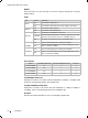
Gigabit Uplink Web Smart Switch 2~5kVA powerline Parallel cabling 300 One is in the grounded metal raceway or metal pipe 150 The both are in the grounded metal raceway or metal pipe 80 >5kVA powerline Parallel cabling 600 One is in the grounded metal raceway or metal pipe 300 The both are in the grounded metal raceway or metal pipe 150 Device Min Distance (m1 Switch case 1.00 Transformer room 2.00 Elevator tower 2.00 Air-conditioner room 2.00 3.
Gigabit Uplink Web Smart Switch CCCCCCCCCC Connection 4444 Ethernet Port Please connect the Ethernet port of the Switch to the network devices by RJ45 cables as the following figure shown.
Gigabit Uplink Web Smart Switch 4444 Verify Installation After completing the installation, please verify the following items: ■■ There are 5~10cm of clearance around the sides of the device for ventilation and the air flow is adequate. ■■ The voltage of the power supply meets the requirement of the input voltage of the device. ■■ The power socket, device and rack are well grounded. ■■ The device is correctly connected to other network devices.
Gigabit Uplink Web Smart Switch CCCCCCCCCC Function Description 5555 System Setting System setting contains the following topics: displaying and configuring the switch information, upgrading firmware, backing up and loading configuration, rebooting and soft-resetting, configuring username and password. 555555 System Setting The system information contains hardware version, software version, system description, system name, system location, contact information and run time.
Gigabit Uplink Web Smart Switch ¾¾ HD: half-duplex, the port supports transmission between the device and the client in only one direction at a time. ¾¾ FD: full-duplex, the port supports transmission between the device and its link partner in both directions simultaneously. Auto negotiation is a protocol between two link partners that enables a port to advertise its transmission rate and duplex mode to its partner.
Gigabit Uplink Web Smart Switch 5555 Network Setting The network module provides the function of setting the switch's IP address, dynamic binding and aging time, configuring static MAC address and filtering MAC address, displaying dynamic bound address and ping. 555555 Network Setting An IP address is indispensable for a switch to be accessed.
Gigabit Uplink Web Smart Switch 555555 Static MAC Address Table A static MAC address table entry contains a MAC address and its corresponding switch port. All the packets taking that MAC address as their destination will be forwarded to the corresponding switch port. The static MAC address won’t age, which differs from the dynamic MAC address. The static MAC address table entry is always valid before it is deleted.
Gigabit Uplink Web Smart Switch 555555 Ping The ping function is to test the connectedness of the link between the switch and destination. 5555 VLAN Setting VLANs are logical subgroups with a Local Area Network (LAN) that combine user stations and network devices into a single unit, regardless of the physical LAN segment to which they are attached. VLANs allow network traffic to flow more efficiently within subgroups.
Gigabit Uplink Web Smart Switch IEEE802.1Q Tag VLAN is divided by VLAN ID (VID). When receiving a frame, the switch checks the VID in the tag header of the frame to decide which VLAN it belongs to. If the receiving frame doesn’t contain the tag header, the switch will assign a tag to the frame, using the PVID of the port as its VID. 3) MTU VLAN MTU VLAN(Multi-Tenant Unit VLAN) defines an uplink port. The uplink port will build up several VLANs with each of the other ports.
Gigabit Uplink Web Smart Switch 555555 Port Default Priority If IEEE802.1p priority mode is configured, when a switch port receives an untagged frame (a frame without priority tag), the port's default priority tag will be inserted into the frame before any other process. 555555 802.1p Priority In IEEE802.1p priority mode, all packets are classified into four priority classes (lowest, lower, higher and highest) according to the embedded priority tag.
Gigabit Uplink Web Smart Switch CCCCCCCCCC WEB Management 6666 Overview The Gigabit Uplink Web Smart Switch is managed via WEB pages. The smart and friendly interfaces make the switch management an easy job. 6666 Connecting to the Device 666666 Getting Started Before connecting to the WEB server (switch), the installation of WEB browser, which supports JavaScript, must be completed in the computer. Due to the difference of parsing syntax, the WEB page shows may differ between variable WEB browsers.
Gigabit Uplink Web Smart Switch Secondly, click the “Settings” button hinted in Figure 6-1, a new dialog will appear: FFFFFFFFFFF Settings Dialog In the case of IE5.0, please check the option “Every visit to the page”; otherwise, some wrong information may show in WEB pages. If the IE version is 6.0, “Every visit to the page” or “Automatically” are both appropriate. Click the “OK” button and complete this setting.
Gigabit Uplink Web Smart Switch A dialog will pop up as below. FFFFFFFFFFF Security Settings Fourthly, Select the “Medium” option of the combo box indicated in Figure 6-4, click the “Reset” button, and click “OK” to quit.
Gigabit Uplink Web Smart Switch Click the “Settings” label, set the screen resolution to 1024 x 768 and click “OK”. All the necessary IE configuration is completed. 666666 Login the Switch Supposing the switch IP address is set as 192.168.0.1, open a web browser and enter http://192.168.0.1 in the address location, and then the following dialog page appears: FFFFFFFFFFF Login Dialog Enter username and password (default value are both "supervisor") to login the switch configuration main page.
Gigabit Uplink Web Smart Switch 222The Port LED Indicator table lies at the top of the page. It provides a visual representation of the ports on the switch front panel to display the status of the ports. The ports, signed with number are the normal ports, signed with GIGA are the Giga ports, signed with SFP are the SFP ports.
Gigabit Uplink Web Smart Switch 333On the left side of the page is the menu table. It contains 8 main menus. Each menu has some submenus. Click on a menu, it will open its submenu and the main window displays the configuration page of the submenu list first. Click on the submenu you want to configure to open the corresponding configuration page. The menu structure is as follows: FFFFFFFFFFFFMain Menu ¾¾ System Setting: System Information, File Transfer, Reboot & Reset, and User.
Gigabit Uplink Web Smart Switch FFFFFFFFFFFFTL-SL2428WEB Main Page FFFFFFFFFFFFTL-SL2452WEB Main Page 666666 System Setting System setting contains four topics: system information, file transfer, reboot & reset and user.
Gigabit Uplink Web Smart Switch ¾¾ Software Version: Displays the installed software version number. ¾¾ Hardware Version: Displays the installed device hardware version number. ¾¾ System Description: Displays the device model number and name. ¾¾ System Name: Defines the user-defined device name. ¾¾ System Location: Defines the location where the system is currently running. ¾¾ Contact Information: Defines the contact information of switch manager. ¾¾ Run time: Shows the run time since last startup.
Gigabit Uplink Web Smart Switch 66666666 Reboot & Reset This page is shown as below. FFFFFFFFFFFFReboot & Reset A prompt is displayed if a button is pressed. For example, if the button “Soft-reset” is pressed, a message box will be activated as shown in Figure 6-20. FFFFFFFFFFFFMessage Box 66666666 User This page provides the interface of configuring username and password.
Gigabit Uplink Web Smart Switch 66666666 Port Parameter This page contains the following fields: FFFFFFFFFFFF Port Parameter ¾¾ Port Status: Indicates whether the port is operational or non-operational. "Enable" indicates the port is operational and "Disable" indicates the port is non-operational. If a port is unused for a long time, it can be set to be non-operational to cut down energy costs. Note: You can't manage the switch via the port, which is non-operational.
Gigabit Uplink Web Smart Switch 66666666 Port Statistic This page displays the port statistic and it contains the following entries: FFFFFFFFFFFFPort Statistic ¾¾ Tx Collisions: The number of collision events experienced by the port. This counter is applicable in half-duplex only. ¾¾ Tx Ucast: The number of frames sent that have a unicast destination MAC address. ¾¾ Tx Mcast: The number of frames sent that have a multicast destination MAC address.
Gigabit Uplink Web Smart Switch ¾¾ RX 128 to 255 B: Total frames received with a length of between 128 and 255 octets inclusive, including those with errors. ¾¾ RX 256 to 511 B: Total frames received with a length of between 256 and 511 octets inclusive, including those with errors. ¾¾ RX 512 to 1023 B: Total frames received with a length of between 512 and 1023 octets inclusive, including those with errors. ¾¾ RX Bytes: The sum of bytes of frames received, not including those with errors.
Gigabit Uplink Web Smart Switch FFFFFFFFFFFFStorm Control ¾¾ Broadcast Control: Enable or disable the broadcast control to limit the broadcast frames. ¾¾ Multicast Control: Enable or disable the multicast control to limit the multicast frames. Enabling multicast control will also enable broadcast control. ¾¾ UL Control: Enable or disable the UL control to limit the UL packets. Enabling UL control will also enable broadcast control and multicast control.
Gigabit Uplink Web Smart Switch 666666 Network Setting This page contains the following topics: switch IP address, static MAC address, filtering MAC address, dynamic binding, bound MAC address, aging time and ping. 66666666 Switch IP Address This page is shown as below: FFFFFFFFFFFFSwitch IP Address ¾¾ MAC Address: Is firmed into switch in the manufacturing process; it is sole and unchangeable. ¾¾ DHCP Client: Indicates whether the DHCP function is enabled.
Gigabit Uplink Web Smart Switch FFFFFFFFFFFFStatic MAC address A MAC address and its corresponding switch port should be provided when adding a static MAC address entry. ¾¾ Search: Input the MAC address in “Mac Address” field and click “Search” button. If that MAC address exists, the following page will appear: FFFFFFFFFFFFA Successful Searching ¾¾ Index: Stands for the entry index of the MAC address in the table. ¾¾ Port: Stands for the switch port number.
Gigabit Uplink Web Smart Switch ■■ There is enough space in static MAC address table. The static MAC address table is divided into several pages. At most 10 entries can be held in one page. The buttons “First”, “Previous” and “Next” can be used to browse the whole table. Note: The capacity of the static MAC address is shown in “Appendix C”.
Gigabit Uplink Web Smart Switch 66666666 Dynamic Binding This page provides the function of enabling or disabling dynamic binding. If dynamic binding is disabled, the switch port learns MAC address unlimitedly (at most 8000 entries can be learned). A switch port with dynamic binding enabled can bind a specified number of MAC address. The MAC addresses bound by the switch port are always valid and won’t age. If the specified number is reached, the port stops binding and transfers into secure state.
Gigabit Uplink Web Smart Switch ¾¾ State: Indicates the switch port state that may be binding, free port, secure port, unplugged or "--". The details are shown below: ■■ ■■ ■■ ■■ ■■ Free Port: The binding function is disabled, and the port can learn MAC address freely. Binding: The port is in binding state, and its bound MAC address number is still less than the max number.
Gigabit Uplink Web Smart Switch Further explanation: The bound MAC address table contains all the MAC addresses bound by the switch ports. Every entry contains one MAC address and its corresponding port number. The bound MAC address table is divided into several pages. At most 10 entries can be held in one page. The buttons “First”, “Previous” and “Next” can be used to browse the whole table.
Gigabit Uplink Web Smart Switch FFFFFFFFFFFFPing ¾¾ Destination IP Address: Indicates the IP Address of the test destination. ¾¾ Ping Count: Indicates the ping times in one submission. ¾¾ Data Size: Indicates the data field length of ping packet. ¾¾ Ping Interval: Indicates the time interval between two continuous pings.
Gigabit Uplink Web Smart Switch 66666666 Port VLAN Setting This page is displayed when the switch is in Port VLAN mode and it contains the following fields: FFFFFFFFFFFFPort VLAN Setting ¾¾ VLAN: The VLAN number. Select the number of the VLAN you want to configure here. ¾¾ Port: The switch port number. ¾¾ Member: Selects the member of the VLAN here. If this field is checked, it indicates the port belongs to the current VLAN. ¾¾ Description: Displays the user-defined port description.
Gigabit Uplink Web Smart Switch 66666666 Tag VLAN Global Setting This page is displayed when the switch is in Tag VLAN mode, the global setting of the ports will affect all Tag VLANs. It contains the following fields: FFFFFFFFFFFFTag VLAN Global Setting ¾¾ Port: The switch port number. ¾¾ PVID: While receiving an untagged frame from the port, the switch will assign a tag to the frame, using the PVID of the port as its VID. ¾¾ Untag Frame: The solution to the untagged frame received.
Gigabit Uplink Web Smart Switch 66666666 Tag VLAN Setting This page is displayed when the switch is in Tag VLAN mode and it contains the following fields. It configures each VLAN and is affected by the global setting of the ports. FFFFFFFFFFFF Tag VLAN Setting ¾¾ VLAN: The VLAN number. Select the number of the VLAN you want to configure here. ¾¾ VLAN ID: Configure the VLAN ID. ¾¾ Port: The switch port number. ¾¾ Member: Select the member of the VLAN here.
Gigabit Uplink Web Smart Switch ¾¾ Clean Up: Clean up all members of the VLAN. ¾¾ Submit: Submit to buildup a VLAN with the selected members. Note: VID of the VLAN must be unique and within the range of 1 to 4094. At least two port members should be included to add a VLAN group. (If the page is submitted with 0 VLAN member, it indicates to delete the VLAN.
Gigabit Uplink Web Smart Switch FFFFFFFFFFFFPort Trunking ¾¾ Trunk: The Trunk number. ¾¾ Member: Select the member of the Trunk here. Each group has 4 optional ports to compose a Trunk. ¾¾ Storm Control: configure the storm control for the Trunk here. All member ports of the Trunk share the same settings. Subfield of the Storm Control are the same as that of the port storm control, see phase 6.3.2.4 for details. ¾¾ Select All: Select all Trunk members in the list.
Gigabit Uplink Web Smart Switch ¾¾ Priority Mode: Contains “Disable”, “Port-Based” and “IEEE802.1p”. ¾¾ Priority Rule: Contains “Weighted” and “Fixed”. If the priority mode is set to be “Disable”, the priority rule cannot be configured. 66666666 Port-Based Priority This page is revealed when the “Port-Based” mode is configured. As shown below. FFFFFFFFFFFFPort-Based priority ¾¾ Port: Indicates the switch port number.
Gigabit Uplink Web Smart Switch 66666666 802.1p Priority Class This page is revealed when the “IEEE802.1p” mode is configured. As shown below: FFFFFFFFFFFF802.1p Priority ¾¾ Priority Tag: The priority tag defined in IEEE802.1p. ¾¾ Corresponding Priority Class: Indicates the inner priority classes of switch. The tagged frames are classified into four classes inside the switch: lowest, lower, higher and highest.
Gigabit Uplink Web Smart Switch Note: Trunk member port can be neither Mirror Port nor Mirrored Port. The Mirror Port can’t be the Mirrored Port at the same time. At most 4 Mirrored Ports can be set. While setting the 100Mbps ports as Mirror Port, it’s not able to select SFP and 1000Mbps ports in the Mirrored Port list. It’s suggested to set the SFP or 1000Mbps ports as Mirror Port. ■■ ■■ ■■ ■■ 666666 Virtual Cable Test The virtual cable test feature enables you test the continuity of the cable circuit.
Gigabit Uplink Web Smart Switch Appendix A Troubleshooting QQQQ Why does the Power LED work abnormally? The Power LED should be lit up when the power system works normally. If the Power LED worked abnormally, please take the following steps: 111 Make sure that the power cable is connected properly, and the power contact is normal. 222 Make sure the voltage of the power supply meets the requirement of the input voltage of the Switch.
Gigabit Uplink Web Smart Switch Appendix B Table of Factory Defaults Table of Factory Defaults: Function Feature System Information System Setting File Transfer User Port Parameter Port Setting Port Statistic Storm Control Port Description Switch IP Address Static MAC Address Default Setting System Name Null System Location Null Contact Information Null Transfer Type System Upgrading File Name SysSL2210WEB.
Gigabit Uplink Web Smart Switch Function VLAN Setting Port Trunking Feature Default Setting VLAN Mode Disable Port VLAN Setting All ports belong to VLAN 1 Tag VLAN Global Setting PVID 1 Untag Frame Pass Tag VLAN Setting All ports belong to VLAN 1; the VID is 1 and “Egress Frame” is "Drop Tag" MTU VLAN Setting Uplink port 1 Priority Mode Disable No configured Trunk Priority Mode Priority Setting Priority Rule Weighted Port-Based Priority Priority Class Lowest Port Default Priorit
Gigabit Uplink Web Smart Switch Appendix C Table of Function Differences of Switch Family Table of Function Differences of Switch Family: Function TL-SL2210WEB TL-SL2218WEB TL-SL2428WEB TL-SL2452WEB Port 10 18 28 52 Giga Port 2 2 4 4 SFP Port 1 1 2 2 Trunk 2 4 6 8 Port VLAN 10 18 28 52 Tag VLAN 64 64 128 256 Static MAC 64 128 128 128 Filtering MAC 64 128 128 128 128 256 384 544 9W MAX 13W MAX 20W MAX 35W MAX Dynamic Binding MAC Power Consumption 53 Mod
Gigabit Uplink Web Smart Switch Appendix D Hardware Specifications Item Content IEEE 802.3 10Base-T IEEE802.3u 100Base-TX Standards and Protocol IEEE802.3ab 1000Base-T IEEE802.3z 1000Base-X IEEE802.3x Flow Control 10Base-T: UTP/STP of Cat. 3 or above Transmission Medium 100Base-TX: UTP/STP of Cat.
Gigabit Uplink Web Smart Switch Appendix E Technical Support ■■ ■■ For more help, please go to: www.tp-link.com/support/faq.asp To download the latest Firmware, Driver, Utility and User Guide, please go to: www.tp-link.com/support/download.asp ■■ 55 For all other technical support, please contact us by using the following details: Global Tel: +86 755 26504400 E-mail: support@tp-link.com Service time: 24hrs, 7 days a week Singapore Tel: +65 62840493 E-mail: support.sg@tp-link.
Website: http://www.tp-link.com E-mail: support@tp-link.com 7106503690 Rev: 2.0.