
User's Guide
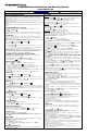

Panel Faults –
If
If If
If Panel Fault icons are
Panel Fault icons are Panel Fault icons are
Panel Fault icons are displayed on the Security screen
displayed on the Security screendisplayed on the Security screen
displayed on the Security screen, contact your alarm company
, contact your alarm company, contact your alarm company
, contact your alarm company. See the full Installation Guide.
. See the full Installation Guide.. See the full Installation Guide.
. See the full Installation Guide.
AC Loss
Bell Failure
Expander Failure
Low Battery
LRR Supervision Failure
1
Max Attempts
Exceeded
Pager Failure
1
Telco-1 Cut
2
Telco-2 Cut
Wireless Failure
Panic
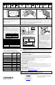
MOUNTING
tuxed ow-0 03-V 0
AM
1:00
Dev ic es
Security
Mu l tim e dia
Saturday, January 28, 2012
Not Ready
P1 H
1:00 AM
N/ A
POWER/RESET
BUTTON
MICRO
SD CARD
SLOT
LED
MOUNTING
PLATE
INSTALL FOUR (4)
MOUNTING SCREWS
DEVICE
WALL
SURFACE
6280W-007-V0
INSERT
SCREWDRIVER
AND TWIST
TO REMOVE DEVICE
FROM MOUNTING
PLATE
SECURING
SCREW
6280W-006-V0
OPERATING THE TOUCHSCREEN
For operating instructions, see the User Guide for the
control panel used with this Touchscreen.
NOTE: If the touchpad is defaulted, it will cause the Z-
Wave module to default.
This TUXEDOW Touchscreen is for indoor use only and should be mounted at a comfortable viewing level. Avoid
mounting in areas of high condensation such as bathrooms or in locations where bright light or sunlight shines
directly on the screen. The Touchscreen is surface mounted directly to a wall.
Locate the mounting plate and attach to a wall using the 4 screws provided. Insert bottom side of Touchscreen
over the mounting plate and then click in top side to snap into place. Install the cover securing screw at the
bottom of the device to secure. The bottom securing screw must be installed.
To remove the Touchscreen from its mounting location, insert the end of a screwdriver between the plate and the
touchscreen and twist to loosen and pull out to remove.
WIRING
CONNECT WIRING
Route wiring from the controller through the opening in the
mounting plate.
Connect the Touchscreen in parallel with Touchscreens
and other peripheral devices using the Touchscreen data
(ECP) bus. If more than one Touchscreen is wired to one
run, then the maximum lengths must be divided by the
number of devices on the run. (e.g., the maximum length
is 75 feet if two devices are wired on a #22 gauge run).
Wire Gauge
Length
#22 gauge 150 feet
#20 gauge 240 feet
#18 gauge 350 feet
#16 gauge 550 feet
BLACK (GND)
RED (+12VDC)
YELLOW
(DATA FROM
CONTROL)
6290W-005-V0
CONTROL
TERMINAL STRIP
AUX DATA
IN
DATA
OUT
AUX
GREEN
(DATA TO CONTROL)
Refer to the control panel Installation Guide for additional
Information.
POWER FROM SUPPLEMENTARY POWER SUPPLY
IF USED
RED
BLACK BLACK
GREEN
YELLOW
CONTROL
TERMINAL STRIP
SUPPLEMENTARY
+12 VDC
POWER SUPPLY
P/N AD12612
DATA
IN
DATA
OUT
AUX
AUX
SUPPLEMENTARY POWER CONNECTIONS
6290W-004-V0
Wi-Fi
®
and the Wi-Fi logo are registered trademarks of Wi-Fi Alliance.
FROM
CONTROLLER
SEE
WIRING
DIAGRAM
6290W-001-V0
This equipment should be installed in accordance with
National Electrical Code, NFPA 70, Standard for the
Installation of Residential Fire Warning Systems,
CAN/ULC-S540 and Chapter 2 of the National Fire
Alarm Code, ANSI/NFPA 72 (National Fire Protection
Association, Batterymarch Park, Quincy, MA 02269).
Printed information describing proper installation,
operation, testing, maintenance, evacuation planning,
and repair service is to be provided with this
equipment.
Warning: Owner’s instruction notice: ’Not to be
removed by anyone except occupant’
This system must be checked by a qualified technician
at least once every three (3) years.
Note: The product should not be disposed of with
other household waste. Check for the nearest
authorized collection centers or authorized recyclers.
The correct disposal of end-of-life equipment will help
prevent potential negative consequences for the
environment and human health.
SPECIFICATIONS
Mechanical Specifications:
Width: 7.91 inches (200.9mm)
Height: 5.04 inches (128.016mm)
Depth: .827 inches (21.00mm)
Electrical specification:
Backlight ON, Sound ON 12V, 270mA
Operating Environment:
Humidity: 93% RH, non-condensing
Operating Temp. 14°F to 131°F / -10°C to 55°C
(UL tested 32°-120°F / 0° to 49°C)
Ship/Storage/Temp.: 40°F to 158°F / -40°C to 70°C
Install in accordance with NFPA-70 and NFPA-72.
Compatibility
The table below identifies the alarm systems that the
Touchscreen can interface with, the maximum number of
Touchscreens that can be used with each system, and the
minimum alarm panel software revision level for compatibility.
Alarm System
Maximum
Number of
Touchscreens
Minimum
Software
Revision
Level
VISTA-15P / 20P 2 3.0
VISTA-20P 4 5.0
VISTA-21P 4 1.0
VISTA-128BP / 250BP / SIA 3 3.2
VISTA-128FBP 3 1.6
VISTA-128FBP-9 / 250FBP-9 3 4.1
VISTA-250FBP 1 1.5
VISTA-250FBP 3 2.0
VISTA-128BPE / 250BPE / SIA 3 4.4
VISTA-128BPEN 3 7.0
VISTA-128FBPN 3 5.1
VISTA-128BPT / 250BPT / SIA 6 10.0
VISTA-32FBPT 6 10.0
Warning: 5G Band 5150-5250 MHz is only for indoor use.
U
L
Use a UL Listed, battery-backed supply for UL installations. The battery supplies power to these keypads in case of
AC power loss. The battery-backed power supply should have enough power to supply the keypads with the UL
required minimum standby power time.
IMPORTANT: Touchscreens powered from supplies that do not have a backup battery do not function if AC power is
lost. Make sure to power at least one keypad in each partition from the control’s auxiliary power output or UL Listed
battery backed up power supply.
FEDERAL COMMUNICATIONS COMMISSION & ISED CANADA STATEMENTS
The user shall not make any changes or modifications to the equipment unless authorized by the Installation Instructions or User's Manual. Unauthorized changes or
modifications could void the user's authority to operate the equipment.
CLASS B DIGITAL DEVICE STATEMENT
This equipment has been tested to FCC requirements and has been found acceptable for use. The FCC requires the following statement for your information.
This equipment generates and uses radio frequency energy and if not installed and used properly, that is, in strict accordance with the manufacturer's instructions,
may cause interference to radio and television reception. It has been type tested and found to comply with the limits for a Class B computing device in accordance
with the specifications in Part 15 of FCC Rules, which are designed to provide reasonable protection against such interference in a residential installation. However,
there is no guarantee that interference will not occur in a particular installation. If this equipment does cause interference to radio or television reception, which can be
determined by turning the equipment off and on, the user is encouraged to try to correct the interference by one or more of the following measures:
• If using an indoor antenna, have a quality outdoor antenna installed.
• Reorient the receiving antenna until interference is reduced or eliminated.
• Move the radio or television receiver away from the receiver/control panel.
• Move the antenna leads away from any wire runs to the receiver/control panel.
• Plug the receiver/control panel into a different outlet so that it and the radio or television receiver are on different branch circuits.
• Consult the dealer or an experienced radio/TV technician for help.
ISED CLASS B STATEMENT
This Class B digital apparatus complies with Canadian ICES-003.
Cet appareil numérique de la classe B est conforme à la norme NMB-003 du Canada.
FCC / ISED STATEMENT
This device complies with Part 15 of the FCC Rules, and ISED’s license-exempt RSSs. Operation is subject to the following two conditions: (1) This device may not
cause harmful interference (2) This device must accept any interference received, including interference that may cause undesired operation.
Cet appareil est conforme à la partie 15 des règles de la FCC et exempt de licence RSS d’ISED. Son fonctionnement est soumis aux conditions suivantes: (1) Cet
appareil ne doit pas causer d' interférences nuisibles. (2) Cet appareil doit accepter toute interférence reçue y compris les interférences causant une réception
indésirable.
Responsible Party / Issuer of Supplier’s Declaration of Conformity: Honeywell International, 2 Corporate Center Dr., Melville, NY 11747, Ph: 516-577-2000.
Partie responsable/Émetteur de la déclaration de conformité du fournisseur: Honeywell International, 2 Corporate Center Drive.,Melville, NY 11747, Tél.516 577-2000
SUPPORT & WARRANTY
For the latest warranty information, please go to:
https://www.security.honeywellhome.com/hsc/resources/wa/index.html
For patent information, see https://www.resideo.com/patent
SUPPORT: For technical support, call 1-800-645-7492 M-F 8:30am to 5pm EST
REFER TO INSTALLATION INSTRUCTIONS FOR THE CONTROL PANEL WITH WHICH THIS DEVICE IS USED FOR
WARRANTY INFORMATION AND LIMITATIONS OF THE ENTIRE ALARM SYSTEM.
UL Note: For residential burglar alarm applications, the entry delay time shall not exceed 15 seconds, therefore use is
restricted to compatible listed control units capable of being programmed for this time parameter.
Connect only keypads to: Aux. + / Aux. - and Data input / Data output.
Ê800-25178dŠ
8
8
0
0
0
0
-
-
2
2
5
5
1
1
7
7
8
8
4
4
-
-
1
1
9
9
R
R
e
e
v
v
.
.
A
A
2 Corporate Center Drive, Suite 100
P.O. Box 9040
Melville, New York 11747
© 2019 Resideo Technologies, Inc
www.resideo.com
This product manufactured by Resideo and its affiliates.
The Honeywell Home Trademark is used under license
from Honeywell International Inc.