17” Quad display LCD monitor ______________________ CHAPTER 1 INTRODUCTION BEFORE INSTALLING YOUR MONITOR READ THIS MANUAL COVER TO COVER. PAY ATTENTION to all WARNING and CAUTIONS DO NOT use computer components not recommend by the manufacture Do not attempt to service the monitor your self. If a problem occurs, contact the manufacture's authorized service cente r ABOUT YOUR MONITOR This monitor is a microprocessor-controlled, color monitor which uses a TFT LCD panel.
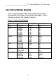
________________________17” Quad display LCD monitor FACTORY-PRESET MODES Table 1 shows standard video mode setting that have been pre-adjusted at the factory for accurate video display. These setting are stored in the monitor's memory Table 1. Factory-Preset Modes Mode NEC VGA SVGA XGA SXGA Macintosh Resolution 640x400 640x350 720x400 640x480 640x480 640x480 800x600 800x600 800x600 800x600 1024x768 1024x768 1024x768 1280x1024 1280x1024 640x480 832x624 1024x768 1024x768 H-Freq.(KHz) 24.83 31.47 31.
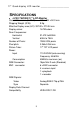
17” Quad display LCD monitor ______________________ SPECIFICATIONS l LCD-1700VRQ 17” LCD Monitor Overall Dimension (HxWxD): 483 x 354 x 50.3 mm Shipping Weight (G/W): 9 Kg Effective Display area (H/V): 337.92 x 270.34 mm Display colors: 16.7M colors Scan Frequencies: Horizontal 31.47K to 80KHz Vertical 60Hz to 75Hz Number of Pixels: 1280x1024 pixels Pixel pitch: 0.264x0.
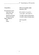
________________________17” Quad display LCD monitor Compatibility: Environmental Limits: Operating Temp Storage Temp.
17” Quad display LCD monitor ______________________ Chapter 2 PRODUCT PACKAGE Open the shipping carton and check the contents. If any items are missing or damaged, contact your dealer immediately. The package should include the following items l l 8U 17” Color TFT LCD Monitor Accessory Box: 1. 2. 3. 4. VGA cable x 1 AC to DC adapter x 1 Power Cord x 1 User’s manual x 1 INSTALLING THE MONIT OR The monitor is equipped with an auto sensing power supply for voltage ranges from 110~240VAC, 60/50Hz.
________________________17” Quad display LCD monitor FOLLOW THESE STEPS T O INSTALL THE MONITOR 1. Before you connect the cables, make sure that the monitor and the system unit power switches are OFF 2. Plug one end of the 15pin signal cable to the monitor and the other end to the video signal connector at the rear of the system. Tighten the two screws on the cable connector on both ends, otherwise the screen will be abnormal and LED light is yellow color, not the normal green color. 3.
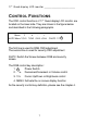
17” Quad display LCD monitor ______________________ C ONTROL F UNCTIONS The OSD control functions of 17” Quad display LCD monitor are located on the lower side. They are shown in the figure below and described in the following paragraphs. Menu ∇ ∆ - + AV/PC Menu ?/CH1 ?/CH2 -/CH3 +/CH4 =/AUTO X The first line is used for RGB OSD adjustment The second line is used for security OSD adjustment AV/PC: Switch the Screen between RGB and security screen. The RGB control key description: 1.
________________________17” Quad display LCD monitor Chapter 3 ADJUSTING THE PC MONITOR The LCD monitor is designed to work with a range of compatible video adapters on the market. Due to the possible deviations between these video adapters, you may make some adjustment to fit the monitor for adapter used.
17” Quad display LCD monitor ______________________ We had two pages OSD screens; the screens are shown in OSD screen 1 and 2, if you choose the source to video not RGB, please see the next chapter.
________________________17” Quad display LCD monitor OSD SCREEN2 1024x768 PREVIOUS PAGE --- Z Brightness -------------RED-------------GREEN---------BLUE ------------- L R G B Contrast --------------RED -------------- R GREEN---------- G BLUE ------------ B 720/640 selection---OSD transparence OSD timeout -----Load Default ---------FIREWARE VERSION 48KHz 60Hz M 0 255 128 P [ ] \ SXGA 5F211-5140 10
17” Quad display LCD monitor ______________________ Adjustment Icon : S @ B H I BL N M P E Auto-adjustment Automatically adjust the pixel clock, H/V position and fine tune the screen to get better visual quality. H-position Adjusts the screen's width. The range is from 0-255. V-Position Adjusts the screen's height. The Range is from 0-255. Pixel Clock Macro-adjust the screen size. The range is from 0-255 Phase Fine tune the screen size to get stable image after you finish the H setting.
________________________17” Quad display LCD monitor F Y Z [ \ ] OSD V-position Change the OSD Vertical Display location in the screen Move to the next OSD screen Move to the previous OSD screen OSD transparency setting To set the OSD display transparency mode. Load default OSD time out timer setting VERTICAL & HORIZONTAL POSITION ADJUSTMENT 1. Use the ∇ & ∆ key to move the 3to the @ICON, then press ﹣ & + to move the whole screen left or right to the center position. 2.
17” Quad display LCD monitor ______________________ BRIGHTNESS ADJUSTMENT 1. Use the ∇ & ∆ key to move the 3to the Licon, then press ﹣ &+ to get the best brightness optimization. Note: We provide another easily method to do the brightness adjustment. You don’t need to activate the OSD screen, just pressing the ﹣ or + to change the brightness value. CONTRAST ADJUSTMENT Adjust the display contrast 1. Use the ∇ & ∆ key to move the 3to the Micon, then press ﹣ & + to get the best brightness optimization.
________________________17” Quad display LCD monitor HOW TO RESTORE THE PRE-DEFINE VALUE Restore your previous define setting 1. Use the ∇ & ∆ key to move the 3to the \ icon, then press “-” will automatically load the pre-define value for each item. 2. Use this function only if you want to discard your new setting. UNDERSTAND THE DISPLAY RESOLUTION SETTING To understand your display mode setting. 1.
” Quad display LCD monitor ______________________ CHAPTER 4 ADJUSTING THE SECURITY SCREEN SETTING The LCD monitor is designed to work with a range of compatible video display on the market. Due to the possible deviations between these video source, you may make some adjustment to fit the monitor for video usage. ADJUSTMENT PROCEDURE 1.
________________________17” Quad display LCD monitor Security OSD menu setting When your screen is in AV mode, pressing MENU key to enter into OSD set up menu, you will see the following screen SETUP MENU SYSTEM CAMERA ALARM PLAYBACK VERSION You can use ?or ? key to move the highlight bar to the desired item, then press = to enter into the sub-menu to change setting.
17” Quad display LCD monitor ______________________ The sub-menu of camera is below CAMERA SETUP CAMERA BRIGHTENSS CONTRAST SHARPNESS SAT U SAT V HUE LOAD DEFAULT CAM1 10 22 55 99 82 01 You can set up each camera brightness, contrast, sharpness, sat U, Sat V and hue setting to the better visual quality. The sub-menu of alarm is below ALARM SETUP AUDIBLE OFF/ON It lets users to set up the audible on of off when camera signal is missing.
________________________17” Quad display LCD monitor Pressing Xto let screen to display 4 channel quad display. Recording the screen will always set as quad display, When you playback the screen, we offered one hot key to let user to see the full channel # display. For example, if you want to see the playback channel 1 in full screen, just pressing ?/CH1, the screen will show the full screen of channel 1.
17” Quad display LCD monitor ______________________ APPENDIX S IGNAL C ONNECTOR PIN - OUT Power Pin 1 Pin 2 Connector Ground +12V output RGB SIGNAL CONNECTOR Pin 1 Analog Red Input Pin 2 Analog Green Input Pin 3 Analog Blue Input Pin 4 Ground Pin 5 Digital Ground Pin 6 Analog Red Ground Pin 7 Analog Green Ground Pin 8 Analog Blue Ground Pin 9 NC Pin 10 Sync Ground Pin 11 Ground Pin 12 SDA ( DDC Data) Pin 13 H. Sync Pin 14 V.