E6581830 TOSVERT VF-S15 series ® option unit Function Manual CCL003Z NOTICE 1. Read this manual before installing or operating. Keep this instruction manual on hand of the end user, and make use of this manual in maintenance and inspection. 2. All information contained in this manual will be changed without notice. Please contact your Toshiba distributor to confirm the latest information.
E658130 Introduction Thank you for purchasing the “CC-Link® option (CCL003Z)” for TOSVERT VF-S15 drive. This option can connect with open field network CC-Link and data communications with the CC-Link master through installing this option in the VF-S15 and using it. Besides this instruction manual, the “CC-Link option Instruction Manual” is required to develop software communicating with VF-S15. This option needs the option adaptor to connect VF-S15 which type form is SBP009Z.
E658130 Handling in general Warning Prohibited Do not connect or disconnect a network cable while the drive power is on. It may lead to electric shocks or fire. Mandatory See the instruction manual attached with the option unit for cautions the handling. Otherwise, it may lead to electric shocks, fire, injuries or damage to product. Network control Warning Prohibited Do not send the value out of the valid range to objects and attributes.
E658130 Table of Contents 1. 2. OVERVIEW ............................................................................................................................................ - 4 BASIC SPECIFICATIONS ..................................................................................................................... - 4 2.1. CC-Link Version .............................................................................................................................. - 5 2.1.1. CC-Link Ver. 1.10 ....
E658130 1. Overview The option allows the VF-S15 drive to be connected into a CC-Link network. CC-Link supports a maximum of 42 nodes, allowing for the Master and this option is based on CC-Link V1.1 and V2.0. The CCL-003Z is able to operate RUN/STOP, monitor the status of the drive, set the drive’s parameter and etc. by the CC-Link master through installing the VF-S15. And it can use various applications. 2.
E658130 2.1. CC-Link Version 2.1.1. CC-Link Ver. 1.10 The conventional CC-Link products, whose inter-station cable lengths have equally been changed to 20cm (7.87 inch) or more to improve the inter-station cable length restriction, are defined as CC-Link Ver. 1.10. In comparison the conventional products are defined as CC-link Ver. 1.00. Refer to the CC-link Master Module Manual for the maximum overall cable lengths and inter-station cable lengths of CC-Link Ver. 1.00 and Ver. 1.10 CC-Link Ver. 1.
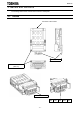
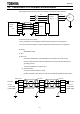
E658130 3. Names and functions The drawing below shows names and functions of main parts. 3.1. Outline Connector to the inverter Release tab LED indicator (See 4.
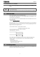
E658130 4. Installation on inverter Refer to VF-S15 option adapter instruction manual (E6581838) for the installation on the inverter. Mandatory The following steps must be performed before installing. 1. Shut off all input power. 2. Wait at least 15 minutes and check to make sure that the charge lamp is no longer lit. 4.1. Connection cable In the CC-Link system, use CC-Link dedicated cables.
E658130 4.3. Connection of CC-Link master unit and inverter The example of the connection of the CC-Link master unit and the inverter is shown.。 Motor U/T1 R/L1 CC-Link Master Unit DA DA DB DB DG DG SLD SLD FG FG S/L2 Inverter V/T2 T/L3 VF-S15 W/T3 IM CCL003Z *Connection of Several Inverters Factory Automation can be applied to several inverters which share a link system as CC-Link remote device stations and are controlled and monitored by PLC user programs.
E658130 4.4. The maximum connection number of units 1. Maximum number of units connected to one master station (CC-Link Ver.1.
E658130 2. Maximum number of units connected to one master station (CC-Link Ver.2.
E658130 4.5. LED indicator The LEDs shows the present status of the network and module Refer to 7.3 for detail. L.RUN SD L.ERR RD ■ Layout of LED L.RUN Light on during communication. SD Light on during send the data of CC-Link. RD Light on during receive the data of CC-Link. L.ERR Light on during communication error.
E658130 5. Functions This option is a communication interface unit that allows the PLC program to operate, monitor and set the parameter of the inverter as a remote station of CC-Link. It is able to communicate with a maximum speed of 10Mbps not only transmitting bit data but also by word data. Moreover, more data transmissions are possible by the use of CC-Link V2.0. 5.1. Initial setting Set the following parameters of the inverter.
E658130 5.2. Communication parameters for CCL003Z Title c100 Function Communication error detection delay time c101 Inverter operation at the communication loss action c102 c103 c120* Preset speed operation selection Communication time-out condition selection CC-Link station number selection Description 0.0 - 100.0 sec.
E658130 5.3. CC-Link function setting 5.3.1. Station number setting Use parameter c120 to set station number of the inverter. Set this parameter within the range of 1 to 64. Title c120 Function Description CC-Link station number selection 1 to 64 *Use different station numbers for different devices. (If different devices have the same station number, the communication cannot be performed properly.) ・ Set consecutive numbers for the station numbers.
E658130 5.3.3. CC-Link extended setting Remote register function can be extended. Title Function c122* CC-Link extended selection Description 0: Occupies one station (V1.10) 1: Occupies one station double (V2.0) 2: Occupies one station quadruple (V2.0) 3: Occupies one station octuple (V2.0) ・ When using double, quadruple and octuple settings of the CC-Link Ver.2, station data of the master station must be set to double, quadruple and octuple also. (If the master station is CC-Link Ver.
E658130 5.4. Basic functions This clause shows the basic function of this CC-Link option using by CC-Link communication. 5.4.1. Run and frequency operation command The PLC program can operate the inverter to run, stop, set the operation frequency and change the parameters. If the PLC controls these operations, select the command mode and the frequency setting mode.
E658130 5.5. I/O signal list 5.5.1. One station is occupied (CC-Link Ver.1) (c122=0) This option occupies one station area of the buffer memory of the PLC. In the case of c122 = 0, there are remote I/O (RX, RY both 32 bits) and the remote register (RWw, RWr both 4 word) in the communication data for one station area. Remote I/O (Default value = 0) Inverter (Slave) → PLC (Master) Device No.
E658130 5.5.2. Double setting is selected (CC-Link Ver.2) (c122=1) This option occupies one station area of the buffer memory of the PLC. In the case of c122 = 1, there are remote I/O (RX, RY both 32 bits(same as CC-LINK Ver.1)) and the remote register (RWw, RWr both 8 word) in the communication data for one station area. * Default value of RY and RX is 0.
E658130 5.5.4. Octuple setting is selected (CC-Link Ver.2) (c122=3) This option occupies one station area of the buffer memory of the PLC. In the case of c122 = 3, there are remote I/O (RX, RY both 32 bits(same as CC-LINK Ver.1)) and the remote register (RWw, RWr both 32 word) in the communication data for one station area. * Default value of RY and RX is 0.
E658130 5.5.5. Trip history When “Quadruple setting” or “Octuple setting” of CC-LINK V.2 is selected, the past trip information can be referred to by the following methods. RWr n+8 RWr n+9 RWr n+A RWr n+B RWr n+C Upper 8 Trip history No.
E658130 5.5.6. Detail of input and output signals 1. Output signals (Master -> Inverter) The output signals from the master unit are indicated. (Input signals to inverter) Device No.
E658130 ■Input function selection from the CC-Link. The function numbers selection of the RYn2 to RYn8 function valid from the command of the CC-Link are following boldface numbers.
E658130 2. Input signal (Inverter -> Master) The following shows input signals to the master unit. (The output signals for the inverter.) Device No..
E658130 5.5.7. Remote Register Assignment Divide the monitor code (RWw n) into half and select the monitor value 1 (RWr n) from the lower 8 bits and the monitor value 2 (RWr n) from the higher 8 bits. For example: When output voltage is selected for the monitor value 1 and output torque is selected for the monitor value 2. -> The monitor code is 0703H. * The hexadecimal value attaches and expresses "H" to the end of a number. 1.
E658130 Address Signal Description Set the command code for actions such as operation mode switching, RWwn+10 Instruction code 2 parameter read, write, error reference, error clear, etc. The command will be executed by turning (RynF) on after the register setting is completed. When the command execution is completed, (RXnF) turns on. Set data specified by the above-mentioned command code 2 RWwn+11 Write data 2 (if necessary). If no data needs to be written, the value shall be zero.
E658130 2. Remote register (Inverter -> Master) RWr Address Signal RWr n Monitor value 1 Description When (RYnC) is on, the monitored value specified to the lower 8 bits of the monitor code (RWwn) is set. When "0" is set to the higher 8 bits of the monitor code (RWwn), the RWrn+1 Monitor value 2 (output frequency) current output frequency is always set.
E658130 Address Signal RWrn+13 Read data 3 Description For a normal reply, the reply data to the instruction specified by the instruction code is set. When (RYnF) is on, the response code correspond to the instruction RWrn+14 Reply code 4 code of (RWw n+14) is set. The value "0" is set for a normal reply and other than "0" is set for data fault, mode error, etc. RWrn+15 Read data 4 For a normal reply, the reply data to the instruction specified by the instruction code is set.
E658130 5.5.8. Instruction Codes Code No.
E658130 Code No. Item 4900H to 6999H Read parameters (RAM) Description To read parameters a900 to c999, 6000H is subtracted from the parameter number. (Ex: A900 A900H – 6000H = 4900H, C123 -> C123H – 6000H = 6123H) A900H to C999H Write parameters (EEPROM&RAM) * To write parameters a900 to c999, the parameter number doesn't change. (Ex: A900 -> A900H, C123 -> C123H) * The Life of EEPROM is approximately 100,000 times.
E658130 5.5.9. The details of an error code The following data are stored as fault history data when the inverter trip occurred. Error code Decimal Hexadecimal No. No.
E658130 Error code Decimal Hexadecimal No. No.
E658130 5.5.10. Description of reply code When executing the frequency setting (RYnD) or instruction code execution (RYnF), check the reply code (RWr (n+2), (n+10), (n+14), (n+16), (n+18)) in the remote register after execution. Reply code Data (Hexadecimal No.) Item 0000H Normal (No error) 0001H Write mode error 0002H 0003H Parameter selection error Setting range error - 32 - Description Normal completion of instruction code execution.
E658130 5.5.11. Description of monitor code Divide the monitor code (RWw n) into half and select the monitor value 1 (RWr n) from the lower 8 bits and the monitor value 2 (RWr n) from the upper 8 bits. For Example: When output voltage is selected for the monitor value 1 and output torque is selected for the monitor value 2. -> The monitor code is 0703H.
E658130 5.5.12. Description of input terminal information Data composition of input terminal information (Code No. = 0FH).
E658130 6. Programming examples This chapter provides programming examples which control the inverter with the PLC. Item Programming Example Refer to Page Reading the inverter status from the buffer 6.1 Reading the inverter status 6.2 Setting the command mode Command mode from CC-Link is confirmed. - 39 - 6.3 Setting the operation commands Commanding the forward rotation. - 40 - 6.4 Setting the reference frequency Setting to 50.00Hz. - 40 - 6.
E658130 2. Network parameter setting of the master station Network parameters are set as below. Item Setting Conditions Item Setting Conditions Start I/O No. 0000 Remote register (RWw) W100 Operation Data link alarm Input clear Special relay (SB) SB0 settings station setting Special resister (SW) SW0 Retry count 3 Automatic reconnection 1 Setting at CPU Refresh stop Type Master station count Mode Remote net CPU down select Stop Ver.
E658130 3. The relation between the device of the 4. The relation between the device of the programmable controller CPU and remote I/O programmable controller CPU and remote register (RX,RY) of the remote device station is as follows: (RWw, RWr) of the remote device station is as The devices used actually are indicated in shaded follows: regions. The devices used actually are indicated in shaded regions.
E658130 6.1. Program example for reading the inverter status Example 1 shows a ladder logic to read the inverter status. Y30 of the output unit is turned on when inverter of station 2 is forward running X0 X0F M0 X1020 X1 SW80.
E658130 6.2. Program example for setting the operation mode Example 2 shows a ladder logic to write data in the inverter. The operation mode of station 1 inverter can be changed to network operation. Operation mode writing code number: 2003H (hexadecimal) Network operation set data: 0004H (hexadecimal) The reply code at the time of instruction code execution is set to D2. X0 X0F X1 SW80.
E658130 6.3. Program example for setting the operation commands Example 3 shows a ladder logic to give a forward command to station 2 inverter. X0 X0F X1 SW80.1 ( M0) M0 Check the ready of the Station 2 X20 (Y1020) Forward rotation command (RY20) Example 3 6.4. Program example for setting the running frequency Example 4 shows a ladder logic to chang the running frequency of station 1 inverter to 50.00Hz Set frequency: X0 X0F X1 5000 (decimal) SW80.
E658130 6.5. Program example for monitoring the output frequency Example 5 shows a ladder logic to read the output frequency of station 1 inveter to D1. Output frequency reading code number: 0001H (hexadecimal) When the output frequency is 50Hz, D1 is 1388H (5000) (unit: 0.01Hz). X0 M0 X0F X1 SW80.0 X20 ( M0) [ MOV H1 W100] ( Y100C) Check the ready of the station 1 Set monitor code (H0001) of output frequency to RWw0.
E658130 6.6. Program example for parameter writing Example 6 shows a ladder logic to chang the setting of f311 of station 1 inverter to 1 f311: Reverse-run prohibition reading code number: 2311H (hexadecimal) Reverse-run prohibition set data: 1 (decimal) X0 M0 X0F X1 SW80.
E658130 6.7. Program example for parameter reading Example 7 shows a ladder logic to read parameter f311 of station 1 inverter to D2. f311: Reverse-run prohibition reading code number: 1311H (hexadecimal) The reply code at the time of instruction code execution is set to D1. X0 M0 X0F X1 SW80.
E658130 6.8. Program example for trip information reading Example 8 shows a ladder logic to read the trip information of station 1 inverter to D1. Trip history No. 1, No. 2 reading code number: 74H (hexadecimal) The reply code at the time of instruction code execution is set to D2. X0 M0 X0F SW80.
E658130 6.9. Program example for resetting the inverter at inverter error Example 9 shows a ladder logic to reset the station 2 inverter. X0 X0F X1 SW80.1 [ M0 M X103 X2 Check the ready of the station 2 Turn on the error reset request flag [Y103A] (RY3A). Then, turn off the error [ END reset request flag (RY3A) when the error Example The above inverter reset using RY3A may be made only when an inverter error occurs. Also, inverter reset can be made independently of the operation mode.
E658130 6.10. Instructions 1.Programming instructions 1.1 Since the buffer memory data of the master station is kept transferred (refreshed) to/from the inverters, the TO instruction need not be executed every scan in response to data write or read requests. The execution of the TO instruction every scan does not pose any problem. 1.2 If the FROM/TO instruction is executed frequently, data may not be written reliably.
E658130 7. Unusual diagnosis 7.1. Option error The error message is displayed when there is hardware error, software error or lose of connection of wire. ▼Display of trip information e-23 (Optional unit fault 2 : 0037H) : Option error 7.2. Disconnection error of network cable ▼Display of trip information err8 (Optional unit fault 1: 001BH): Network error stop *If a network error occurs when c101 is set to "4", it is displayed.
E658130 7.3. How to check the error using the LEDs The following example explains the causes of fault which may be judged from the LED status of the CC-Link unit (CCL003Z) of the inverter. 1.
E658130 2.
E658130 3. Communication stops during operation ▪ Check that the CC-Link units and the CC-Link dedicated cable are connected properly. (Check for contact fault, break in the cable, etc.) ▪ Check that the PLC program is executed properly. ▪ Check that data communication has not stopped due to an instantaneous power failure, etc. LED Status Master TIME○ LINE○ or TIME● LINE○ TIME● LINE● or TIME○ LINE● CCL003Z Cause Corrective Action The station numbers of station 1 and 3 are duplicated.