NETWORK CAMERA Model: IK-WR14A Quick Start Guide and Important Safeguards This guide describes the hardware installation. Refer to the user's manual (PDF file) contained in the CD-ROM for settings, operations and other information. The application Adobe Reader is needed to view PDF files. If you do not have this application, download it from the Adobe Systems Incorporated website. n http://www.adobe.
Introduction FCC (USA)-INFORMATION NOTE: This equipment has been tested and found to comply with the limits for a Class A digital device, pursuant to Part 15 of the FCC Rules. These limits are designed to provide reasonable protection against harmful interference when the equipment is operated in a commercial environment.
Thank you for purchasing the IK-WR14A Network Camera. Before using the camera, read this quick start guide carefully to ensure correct usage. After reading this quick start guide, save it for future reference. The design, specifications, software, and quick start guide contents are subject to change without prior notice. Terms and Trademarks l The term "OS" is used in this manual to indicate operating systems compatible with this product.
Table of Contents Introduction 2 FCC (USA)-INFORMATION ���������������������������������������������������������������������������������������2 Terms and Trademarks ����������������������������������������������������������������������������������������������3 Table of Contents ��������������������������������������������������������������������������������������������� 4 Important Safeguards ��������������������������������������������������������������������������������������� 5 Important Safeguards
Important Safeguards 1. Read Instructions Read all the safety and operating instructions before operating the product. 2. Retain Instructions Retain the safety instructions and user's manual for future reference. 3. Warnings Comply with all warnings on the product and in the user's manual. 4. Follow Instructions Follow all operating and use instructions. 5. Cleaning Disconnect this camera from the power supply before cleaning. 6.
12. Lightning For additional protection on this camera during a lightning storm, or when it is left unattended and unused for long periods of time, unplug it from the wall outlet and disconnect the power supply and cable system. This will prevent damage to the camera due to lightning and power-line surges. If lightning occurs, do not touch the unit or any connected cables in order to avoid electric shock. 13.
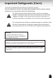
Important Safeguards (Cont.) CAUTION TO REDUCE THE RISK OF ELECTRIC SHOCK. DO NOT REMOVE COVER. NO USER SERVICEABLE PARTS INSIDE. REFER SERVICING TO QUALIFIED SERVICE PERSONNEL. The lightning flash with arrowhead symbol, within an equilateral triangle, is intended to alert the user to the presence of uninsulated "dangerous voltage" within the product's enclosure that may be of sufficient magnitude to constitute a risk of electric shock to persons.
Notes on Use and Installation l Do not aim the camera at the sun Never aim the camera at the sun even with the camera power off. l Do not shoot intense light Intense light such as a spotlight may cause a bloom or smear. A vertical stripe may appear on the screen. However, this is not a malfunction. l Treat the camera with care Dropping or subjecting the camera to intense vibration may cause it to malfunction.
Setting the Network Camera Environment Items needed for network camera monitoring l Administrator's personal computer The personal computer that allows setting, operating, monitoring and other functions with the network camera is called the "administrator's personal computer" in this guide. * The personal computer for viewing monitored images is called the "user's personal computer" in this quick start guide. The network camera can be viewed by more than one personal computer at the same time.
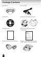
Package Contents l IK-WR14A l AV Out cable l CD-ROM l Alignment Sticker/Mounting Plate l Warranty Card l Quick Start Guide and Important Safeguards l Waterproof Connector & Bushing l Gasket, Torx Wrench, Silica Gel and tape, Hex Nut , Screws and Anchors 10
Physical Description Camera Base Dome Cover Cover screws Side Opening Cover NOTE Replace the side opening cover with the supplied bushing if you want to route cables from the side of camera. The 1/2" (12.7mm) protection conduits and tubing are not supplied.
CAMERA BASE l Front View IR LEDs (SR-LED) Lens Light Sensor Focus Button Lens cover Tilt adjustment screws Mounting screws Status LED l Rear View General I/O Terminal Block Micro SD/ SDHC Card Slot 1. GND 2. Power input (DC 12V) 3. Power input (AC 24V) 4. Power input (AC 24V) 5. Signal GND 6. Digital Input 7. Digital output 8.
Hardware Installation First, use the supplied torx wrench to detach the dome cover from the camera base. Then, follow the steps below to install the camera; either to a ceiling or to a wall. Bottom of the Camera NOTE Record the MAC address under the camera base before installing the camera. Cabling Assembly Connect the appropriate power cables and external devices such as sensors and alarms, to the general I/O terminal block. Top View Power and IO cables pass through a waterproof connector.
Waterproof Connector (A) Sealing Nut (A) Housing (B) (B) (D) Seals (C) Seal (D) (E) Screw Nut (E) Hex Nut (F) (F) Assembling Steps 1. D i s a s s e m b l e t h e c o m p o n e n t s o f t h e waterproof connector into parts (A) ~ (E) as shown above. And Hex Nut is including in the accessory separately. 2. Place the screw nut (E) as shown. 3. F e e d t h e p o w e r c a b l e s t h r o u g h t h e waterproof connector (F --> E --> D --> B --> A) as the illustration shows.
3. You will need an RJ45 crimping tool to attach the Ethernet wires to a connector. When done, connect the cable to the camera’s Ethernet socket . 3 o: white/orange stripe O: orange solid g: white/green stripe B: blue solid b: white/blue stripe G: green solid br: white/brown stripe BR: brown solid o O g B b G br BR NOTE 1 2 3 4 5 6 7 8 l l RJ45 crimping tool and plug are not included. Use Category (Cat) 5e or higher cable. 4.
1 3 2 5 A B CAUTION l Installation should be done only by qualified personnel and conform to all local codes. l Install this camera on a firm and solid part of the ceiling or wall. If installed improperly or on a weak surface, the camera could fall causing injury and damage.
Network Deployment Power over Ethernet (PoE) l When using a PoE-enabled switch The camera is PoE-compliant, allowing transmission of power and data via single LAN cable. See the following illustration to connect the camera to a PoE switch via LAN cable. KNIL EVIECER NOITITRAP 4 5 3 2 1 NOISILLOC REWOP Client PC (not supplied) PoE switch (not supplied) l When using a non-PoE switch Use a PoE power injector (not supplied) to connect between the camera and a non-PoE switch.
General Connection (without PoE) 1. Connect the camera to an Ethernet switch via LAN cable. 2. Connect the power cable from a power unit (not supplied) to the appropriate port of the general I/O terminal. (See page 12). 3. Connect the PC to an Ethernet switch via Ethernet cable.
Assigning IP Address 1. Install the "Installation Wizard" under the Software Utility directory from the CDROM. 2. The program will analyze your network environment. After your network is analyzed, please click on the "Next" button to continue the program. Installation Wizard 3. The program searches for other Network Cameras on the same network. 4. After searching, the main installer window will pop up. Click on the MAC address of the appropriate device to connect to the Network Camera.
Retrieving Images 1. Access the Network Camera from the network. 2. Retrieve live video through Internet Explorer®. For more information on camera configuration, please refer to user's manual on the CD-ROM.
Adjusting the Lens Based on the live image retrieved from the camera, adjust the camera lens by performing the following: To adjust the viewing angle 1. Turn the lens module left and right. 2. Loosen the tilt adjustment screws on both side of the camera and then turn the lens module up and down. Upon completion, tighten the screws. 3. Turn the lens cover to adjust the image orientation. NOTE l Do not cover or block the IR LEDs or the light sensor with status LED board.
Dome cover 1. Attach the dome cover to the camera and aligning with the mounting holes. 2. You will find a silica gel bag attached to the dome cover. Remove the supplied silica gel from the aluminum foil bag, and replace it to new silica gel with supplied double-sided tape. (Please replace the silica gel with a new one if you open the dome cover after installation.) 3. Secure the four dome screws with the supplied torx wrench. Make sure all parts of the camera are securely installed.
Adjusting the Zoom and Focus Access the Network Camera from the browser interface, and click the configuration button onthe main page. Then click the following: Audio and Video Image Zoom and Focus To adjust the zoom factor and focus range 1. Use the Zoom slide bar to find an optimal view of the area of interest where you want to adjust its focus. Click and drag the double-triangle pointer to rapidly adjust the zoom ratio. The Focus pointer moves with the Zoom pointer correspondingly. 2.
TOSHIBA AMERICA INFORMATION SYSTEMS, INC.