
User Guide


4 Replacement Procedures
4-iv Satellite P10 PSP13*/16* Series Maintenance Manual
Figures
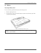
Figure 4-1 Removing the battery pack ......................................................................................4-7
Figure 4-2 Pressing the eject button..........................................................................................4-9
Figure 4-3 Installing the PC Card............................................................................................4-10
Figure 4-4 HDD.....................................................................................................................4-11
Figure 4-5 Removing the HDD door.......................................................................................4-11
Figure 4-6 Removing the optical drive module.........................................................................4-13
Figure 4-7 Removing the optical drive bracket ........................................................................4-15
Figure 4-8 Removing the mini PCI bracket..............................................................................4-17
Figure 4-9 Removing the wireless LAN unit ............................................................................4-18
Figure 4-10 Removing the expansion memory...........................................................................4-20
Figure 4-11 Removing the expansion memory cover..................................................................4-21
Figure 4-12 Installing the expansion memory.............................................................................4-22
Figure 4-13 Removing the strip cover .......................................................................................4-23
Figure 4-14 Removing the keyboard.........................................................................................4-24
Figure 4-15 Disconnecting the keyboard cable..........................................................................4-25
Figure 4-16 Removing the modem module ................................................................................4-26
Figure 4-17 Removing the LCD display cable ...........................................................................4-29
Figure 4-18 Pulling the wireless LAN antenna wires..................................................................4-29
Figure 4-19 Removing the top cover-1 .....................................................................................4-31
Figure 4-20 Removing the top cover-2 .....................................................................................4-32
Figure 4-21 Removing the touch pad ........................................................................................4-34
Figure 4-22 Removing the speakers..........................................................................................4-36
Figure 4-23 Removing the system board-1................................................................................4-37
Figure 4-24 Removing the system board-2................................................................................4-37
Figure 4-25 Removing the fan module.......................................................................................4-39
Figure 4-26 Removing the heat sink ..........................................................................................4-40
Figure 4-27 Removing the CPU................................................................................................4-40
Figure 4-28 Removing the display mask....................................................................................4-42
Figure 4-29 Removing the LCD module-1................................................................................4-44