User’s Manual Qosmio G20
Copyright © 2005 by TOSHIBA Corporation. All rights reserved. Under the copyright laws, this manual cannot be reproduced in any form without the prior written permission of TOSHIBA. No patent liability is assumed, with respect to the use of the information contained herein.
Trademarks IBM is a registered trademark and IBM PC is a trademark of International Business Machines Corporation. Intel, Intel SpeedStep, Centrino and Pentium are trademarks or registered trademarks of Intel Corporation. Windows and Microsoft are registered trademarks of Microsoft Corporation. Photo CD is a trademark of Eastman Kodak. Sonic RecordNow! and Sonic PrimeTime are registered trademarks of Sonic Solutions. Bluetooth is a trademark owned by its proprietor and used by TOSHIBA under license.
Modem warning notice Conformity Statement The equipment has been approved to [Commission Decision “CTR21”] for pan-European single terminal connection to the Public Switched Telephone Network (PSTN). However, due to differences between the individual PSTNs provided in different countries/regions the approval does not, of itself, give an unconditional assurance of successful operation on every PSTN network termination point.
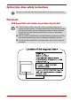
Optical disc drive safety instructions Be sure to check the international precautions at the end of this section. Panasonic DVD Super Multi with Double Layer Recording UJ-846 ■ The DVD Super Multi drive with Double Layer Recording model employs a laser system. To ensure proper use of this product, please read this instruction manual carefully and retain for future reference. Should the unit ever require maintenance, contact an authorized service location.
International precautions CAUTION: This appliance contains a laser system and is classified as a “CLASS 1 LASER PRODUCT.” To use this model properly, read the instruction manual carefully and keep this manual for your future reference. In case of any trouble with this model, please contact your nearest “AUTHORIZED service station.” To prevent direct exposure to the laser beam, do not try to open the enclosure.
OBS! Apparaten innehåller laserkomponent som avger laserstråining överstigande gränsen för laserklass 1. VAROITUS. Suojakoteloa si saa avata. Laite sisältää laserdiodin, joka lähetää näkymätöntä silmilie vaarallista lasersäteilyä. CAUTION: USE OF CONTROLS OR ADJUSTMENTS OR PERFORMANCE OF PROCEDURES OTHER THAN THOSE SPECIFIED IN THE OWNER’S MANUAL MAY RESULT IN HAZARDOUS RADIATION EXPOSURE.
viii User’s Manual
Table of Contents Preface General Precautions Chapter 1 Introduction Equipment checklist. . . . . . . . . . . . . . . . . . . . . . . . . . . . . . . . . . . . . . . 1-1 Features. . . . . . . . . . . . . . . . . . . . . . . . . . . . . . . . . . . . . . . . . . . . . . . . . 1-4 Special features . . . . . . . . . . . . . . . . . . . . . . . . . . . . . . . . . . . . . . . . . . 1-9 Utilities. . . . . . . . . . . . . . . . . . . . . . . . . . . . . . . . . . . . . . . . . . . . . . . . . 1-12 Options . . .
Chapter 4 Operating Basics Using the Touch Pad . . . . . . . . . . . . . . . . . . . . . . . . . . . . . . . . . . . . . . .4-1 Using the USB floppy disk drive (optional) . . . . . . . . . . . . . . . . . . . . .4-2 TV Tuner . . . . . . . . . . . . . . . . . . . . . . . . . . . . . . . . . . . . . . . . . . . . . . . . .4-3 Sound System . . . . . . . . . . . . . . . . . . . . . . . . . . . . . . . . . . . . . . . . . . . .4-5 Writing CDs/DVDs on DVD Super Multi drive . . . . . . . . . . . . . . . . . . .
Chapter 8 Using the Remote Controller, Front operation panel and QosmioPlayer Windows XP Media Center Edition and QosmioPlayer. . . . . . . . . . . 8-1 Remote Controller . . . . . . . . . . . . . . . . . . . . . . . . . . . . . . . . . . . . . . . . 8-2 Front operation panel function . . . . . . . . . . . . . . . . . . . . . . . . . . . . . . 8-6 Using the Remote Controller . . . . . . . . . . . . . . . . . . . . . . . . . . . . . . . 8-10 Installing/Removing batteries . . . . . . . . . . . . . . . . . . .
Appendix D Bluetooth wireless technology Interoperability Bluetooth wireless technology and your Health . . . . . . . . . . . . . . . . D-3 Regulatory statements. . . . . . . . . . . . . . . . . . . . . . . . . . . . . . . . . . . . . D-3 Approved Countries/Regions for use (Bluetooth™ wireless technology) . . . . . . . . . . . . . . . . . . . . . . . . . . . D-6 Appendix E TOSHIBA RAID Setting up Windows Manually. . . . . . . . . . . . . . . . . . . . . . . . . . . . . . .
Preface Congratulations on your purchase of the Qosmio G20 computer. This powerful notebook computer provides excellent expansion capability, including multimedia devices, and it is designed to provide years of reliable, high-performance computing. This manual tells how to set up and begin using your Qosmio G20 computer. It also provides detailed information on configuring your computer, basic operations and care, using optional devices and troubleshooting.
Preface Chapter 6, Power, gives details on the computer’s power resources and battery save modes. Chapter 7, HW Setup, explains how to configure the computer using the HW Setup program. Chapter 8, Using the Remote Controller, Front operation panel and QosmioPlayer, explains how to use the Remote Controller as well as provides information about QosmioPlayer. Chapter 9, Optional Devices, describes the optional hardware available.
Preface Key operation Some operations require you to simultaneously use two or more keys. We identify such operations by the key top symbols separated by a plus sign (+). For example, Ctrl + C means you must hold down Ctrl and at the same time press C. If three keys are used, hold down the first two and at the same time press the third.
Preface xvi User’s Manual
General Precautions TOSHIBA computers are designed to optimize safety, minimize strain and withstand the rigors of portability. However, certain precautions should be observed to further reduce the risk of personal injury or damage to the computer. Be certain to read the general precautions below and to note the cautions included in the text of the manual. Stress injury Carefully read the Instruction Manual for Safety & Comfort.
General Precautions Mobile phone Use of mobile phones can interfere with the audio system. Computer operation is not impaired but is recommended that a distance of 30 cm be maintained between the computer and a mobile phone in use. Disclaimers LCD Over a period of time, and depending on the usage of the computer, the brightness of the LCD screen will deteriorate. This is an intrinsic characteristic of LCD technology. Maximum brightness is only available when operating in AC power mode.
General Precautions HDD Drive Capacity 1 Gigabyte (GB) means 1000 × 1000 × 1000 = 1,000,000,000 bytes using powers of 10. The computer operating system, however, reports storage capacity using powers of 2 for the definition of 1 GB = 1024 × 1024 × 1024 = 1,073,741,824 bytes, and therefore may show less storage capacity.
General Precautions Safety Use for TV Tuner If you have to operate your PC during a thunderstorm and are connecting the TV tuner to an outside antenna, you should operate your PC using AC power mode. The AC adapter offers some protection against (but does not entirely prevent) possible electric shock caused by lightning. For complete protection, do not operate your PC during a thunderstorm.
General Precautions The cautions on use of a Qosmio G20 series computer 1. Cleaning of dust accumulated on the cooling vent of the computer. When you use your computer in a dusty area, dirt and debris may accumulate on the cooling vents at the underside. If this occurs, the accumulated dust can cause insufficient heat dissipation which may result in the computer shutting down during use. Carefully clean the dust from the vents using a vacuum cleaner. 2. Cooling vents on the underside of the computer.
General Precautions xxii User’s Manual
Chapter 1 Introduction This chapter provides an equipment checklist, and it identifies the computer’s features, options and accessories. Some of the features described in this manual may not function properly if you use an operating system that was not preinstalled by TOSHIBA. Equipment checklist Carefully unpack your computer. Save the box and packing materials for future use.
Introduction Software Microsoft®Windows XP Media Center Edition ■ The following software is preinstalled: ■ Microsoft® Windows XP Media Center Edition 2005 Update Rollup 2 ■ TOSHIBA Utilities ■ DVD Video Player ■ TOSHIBA Power Saver ■ TOSHIBA Assist ■ TOSHIBA Controls ■ TOSHIBA PC Diagnostic Tool ■ TOSHIBA Touch and Launch ■ TOSHIBA TouchPad On/Off Utility ■ TOSHIBA Zooming Utility ■ TOSHIBA Picture Enhancement Utility ■ TOSHIBA ConfigFree ■ TOSHIBA SD Memory Card Format ■ TOSHIBA Acoustic Silencer ■ TOSHI
Introduction If any of the items are missing or damaged, contact your dealer immediately.
Introduction Features The computer uses TOSHIBA’s advanced Large Scale Integration (LSI), Complementary Metal-Oxide Semiconductor (CMOS) technology extensively to provide compact size, minimum weight, low power usage, and high reliability. This computer incorporates the following features and benefits: Processor Built-in The computer is equipped with an Intel® Pentium® M processor, which incorporates a 2MB level 2 cache memory. It also supports Enhanced Intel® SpeedStepTM technology.
Introduction Disks Hard disk drive Available in four sizes. ■ 60.0 billion bytes (55.88 GB) ■ 80.0 billion bytes (74.52 GB) ■ 100.0 billion bytes (93.16GB) ■ 120.0 billion bytes (111.76GB) Depending on your configuration, your computer is equipped with either one or two hard disk drives. Other hard disk drives may be introduced.
Introduction Pointing Device Built-in Touch Pad A Touch Pad and control buttons in the palm rest enable control of the on-screen pointer and scrolling of windows. Ports External monitor Analog VGA port supports VESA DDC2B compatible functions. Universal Serial Bus (USB 2.0) The computer has Universal Serial Bus ports that comply with the USB 2.0 standard, which enables data transfer speeds 40 times faster than the USB 1.1 standard (The ports also support USB 1.1). i.
Introduction User’s Manual TV antenna port This port is available on configurations with built-in TV Tuner only. Connect the antenna adaptor to this port to watch TV programs on your computer or record them. S-Video in Port A camcorder or other recording device can be connected to your computer via an S-Video in cable (optional) for importing video data. Connect the cable to this port. Refer to the S-Video-in section in Chapter 9, Optional Devices.
Introduction Communications 1-8 Modem An internal modem provides capability for data and fax communication. It supports V.90 (V.92). The speed of data transfer and fax depends on analog telephone line conditions. It has a modem jack for connecting to a telephone line. Both of V.90 and V.92 are supported only in USA, Canada, UK, France, Germany and Australia. Only V.90 is available in other regions.
Introduction ■ The numerical values shown above are the theoretical maximums for Wireless LAN standards. The actual values may differ. ■ The transmission speed over the wireless LAN and the distance over which wireless LAN can reach may vary depending on surrounding electromagnetic environment, obstacles, access point design and configuration, and client design and software/hardware configurations. The Transmit Rate (at X Mbit/s) is the theoretical maximum speed under the IEEE802.11 (a/b/g) standard.
Introduction 1-10 HDD automatic power off This feature automatically cuts off power to the hard disk drive when it is not accessed for a time specified. Power is restored when the hard disk is accessed. You can specify the time in the HDD power off item of the Basic Setup tab in TOSHIBA Power Saver. System automatic Standby/Hibernation This feature automatically shuts down the system into Standby Mode or Hibernation Mode when there is no input or hardware access for a time specified.
Introduction User’s Manual Low battery automatic hibernation When battery power is exhausted to the point that computer operation cannot be continued, the system automatically enters Hibernation and shuts down. You can specify the setting in the Setup Action tab in TOSHIBA Power Saver. Heat dispersal To protect from overheating, the CPU has an internal temperature sensor. If the computer’s internal temperature rises to a certain level, the cooling fan is turned on or the processing speed is lowered.
Introduction Utilities This section describes preinstalled utilities and tells how to start them. For details on operations, refer to each utility’s online manual, help files or readme.txt files. TOSHIBA Power Saver To access this power savings management program, click start, click the Control Panel, click Performance and Maintenance and select the TOSHIBA Power Saver icon.
Introduction RecordNow! Basic for TOSHIBA You can create CD/DVDs in several formats including audio CDs that can be played on a standard stereo CD player and data CD/DVDs to store the files and folders on your hard disk drive. DLA for TOSHIBA DLA (Drive Letter Access) is the packet writing software which provides the function which writes files and/or folders to DVD-RW, CD-RW and DVD+RW discs via a drive letter (like a floppy disk or other removable disks).
Introduction 1-14 TOSHIBA RAID Console Use the TOSHIBA RAID Console to create or manage a RAID array. To start the utility, click start, point to All Programs, point to TOSHIBA, point to RAID and click RAID Console. It is possible to change to RAID1 (mirroring) from a non-RAID configuration. To change to RAID0 (striping), restore your pre-installed software using the Product Recovery DVD-ROM. Please refer to Restoring the Preinstalled Software section in Chapter 3, Getting Started, for details.
Introduction Options You can add a number of options to make your computer even more powerful and convenient to use. The following options are available: User’s Manual Memory expansion A 256, 512 or 1,024 MB memory module (DDR2 533) can easily be installed in the computer. Battery pack An additional battery pack can be purchased from your TOSHIBA dealer. Use it as a spare or replacement.
Introduction 1-16 User’s Manual
Chapter 2 The Grand Tour This chapter identifies the various components of your computer. Become familiar with each component before you operate the computer. Certain notebook chassis are designed to accommodate all possible configurations for an entire product series. Therefore, please be aware that your selected model may not have all the features and specifications corresponding to all of the icons or switches shown on the notebook chassis.
The Grand Tour Front with the display closed The following figure shows the computer’s front with its display panel in the closed position. Optical media drive Indicators (1) Display latch Infrared receiver window Front of the computer with display closed Optical media drive The computer is configured with a DVD Super Multi drive. Display latch This latch secures the LCD panel in its closed position. Push the latch to open the display.
The Grand Tour ■ In case of a lightning storm, unplug the modem cable from the telephone jack. ■ Do not connect the modem to a digital telephone line. A digital line will damage the modem. Universal Serial Bus (USB 2.0) ports Two Universal Serial Bus ports are on the left side. The ports comply with the USB 2.0 standard, which enables data transfer speeds 40 times faster than the USB 1.1 standard (The ports also support USB 1.1). Keep foreign objects out of the USB connectors.
The Grand Tour Right side The following figure shows the computer’s right side. ExpressCard slot ExpressCard eject button PC card slot PC card eject button Bridge media slot i.LINK (IEEE1394) port The right side of the computer Bridge media slot This slot lets you insert an SD card, Memory Stick (Pro), xD picture card and MultiMediaCard. Refer to Chapter 9, Optional Devices. Keep foreign objects out of the Bridge media slot. A pin or similar object can damage the computer’s circuitry.
The Grand Tour Back side The following figure shows the computer’s back side. LAN active indicator (orange) DC IN 15V jack D-Video out port Security lock slot TV antenna port Cooling vents USB ports Link indicator (green) Monitor-in port S-Video out port Cooling vents External monitor port LAN jack S-Video in port The back side of the computer Security lock slot A security cable attaches to this slot.
The Grand Tour External monitor port This external monitor port lets you connect an external video display. Universal Serial Bus (USB 2.0) ports Two Universal Serial Bus ports are on the backside. Refer to Left side section, for details. These ports are located near the cooling vents. Areas near the cooling vents get very hot. Check the guaranteed operating temperatures of your USB device when you place it close to these areas or put it at a remote location via an extension cable.
The Grand Tour Underside The following figure shows the underside of the computer. Make sure the display is closed before turning over your computer. Battery lock Battery pack Memory module cover Battery release latch HDD2 HDD1 The underside of the computer User’s Manual Memory module cover This cover protects memory module sockets. Refer to the Memory expansion section in Chapter 9, Optional Devices.
The Grand Tour Hard Disk Drive 2 If your model has two hard disk drives, this cover protects the secondary Hard disk drive pack. The secondary pack can be removed and reinstalled. For more information on how to remove or reinstall the Hard disk drive pack, refer to the section on the Hard disk drive pack in Chapter 9, Optional Devices. Front with the display open This section shows the front of the computer with the display open. Refer to the appropriate illustration for details.
The Grand Tour Display screen The LCD displays high-contrast text and graphics. The computer’s WXGA+ screen consists of 1440 × 900 pixels. Refer to Appendix B, Display Controller and Modes. When the computer operates on the AC adaptor the display screen’s image will be somewhat brighter than when it operates on battery power. The lower brightness level is intended to save battery power. Microphone The built-in microphone lets you record sounds into your applications.
The Grand Tour Touch Pad A Touch Pad located in the palm rest is used to control the on-screen pointer. Refer to the Using the Touch Pad section in Chapter 4, Operating Basics. Touch Pad control buttons Control buttons below the Touch Pad let you select menu items or manipulate text and graphics designated by the on-screen pointer. LCD Sensor switch This switch senses when the LCD panel is closed or opened and activates the Panel Power Off/On feature.
The Grand Tour Indicators This section describes the indicators. System indicators The following indicators on the front of the computer can be monitored even when the display panel is closed. DC IN Power Battery System indicators (1) User’s Manual DC IN The DC IN indicator glows blue when DC power is supplied from the AC power adaptor. If the adaptor’s output voltage is abnormal or if the power supply malfunctions, this indicator flashes orange.
The Grand Tour Optical Media Drive HDD Bridge media slot Wireless communication System indicators (2) 2-12 HDD The Hard Disk Drive indicator glows blue when the computer is accessing the built-in hard disk Optical media drive The Optical media drive indicator glows blue when the computer is accessing a disk in the DVD Super Multi drive. Bridge media slot The Bridge media slot indicator glows blue when the computer is accessing the Bridge media slot.
The Grand Tour Keyboard indicators The figures below show the positions of the keypad overlay indicators and the Caps Lock indicator. The following indicator shows the state of an alphabet key (pressed or released). Caps Lock indicator Caps Lock indicator Caps Lock The Caps Lock indicator glows green when the alphabet keys are locked in uppercase. The following indicators show the status of the keypad overlay.
The Grand Tour Volume indicator This indicator employs a 6 stage lighting method to indicate the level of volume. By turning the volume dial you can turn the indicator lights on and off. If you want to increase the volume, move the dial from right to left (counterclockwise) and the 6 stages will flash in order. If you want decrease the volume, move the dial from left to right (clockwise) and the indicator lights will go out.
The Grand Tour Check the Disk-In-Use indicator when you use the floppy disk drive. Do not press the eject button or turn off the computer while the light is glowing. Doing so could destroy data and damage the floppy disk or the drive. ■ The external floppy disk drive should be placed on a flat, horizontal surface when in use. Do not set the drive on an incline greater than 20° while it is operating. ■ Do not set anything on top of the floppy disk drive.
The Grand Tour DVDs ■ DVD-R and DVD+R discs can be written only once. The recorded data cannot be erased or changed. ■ DVD-RW, DVD+RW and DVD-RAM discs can be recorded more than once.
The Grand Tour AC adaptor The AC adaptor can automatically adjust to any voltage ranging from 100 to 240 volts and to a frequency of either 50 or 60 hertz, enabling you to use this computer in almost any country/region. The adaptor converts AC power to DC power and reduces the voltage supplied to this computer. To recharge the battery, simply connect the AC adaptor to a power source and the computer. Refer to Chapter 6, Power, for details.
The Grand Tour 2-18 User’s Manual
Chapter 3 Getting Started This chapter provides basic information to get you started using your computer. It covers the following topics: ■ Setting up your work space — for your health and safety Be sure also to read the Instruction Manual for Safety & Comfort. This guide, which is included with the computer, explains product liability.
Getting Started General conditions In general, if you are comfortable, so is your computer, but read the following to make sure your work site provides a proper environment. ■ Make sure there is adequate space around the computer for proper ventilation. ■ Make sure the AC power cord connects to an outlet that is close to the computer and easily accessible. ■ The temperature should be 5 to 35 degrees Centigrade (41 to 95 degrees Fahrenheit) and the relative humidity should be 20 to 80 percent.
Getting Started Seating and posture The height of your chair in relation to the computer and keyboard as well as the support it gives your body are primary factors in reducing work strain. Refer to the following tips. Below eye level 90°angles Foot rest Posture and positioning of the computer ■ Place your chair so that the keyboard is at or slightly below the level of your elbow. You should be able to type comfortably with your shoulders relaxed. ■ Your knees should be slightly higher than your hips.
Getting Started Work habits A key to avoiding discomfort or injury from repetitive strain is to vary your activities. If possible, schedule a variety of tasks into your workday. If you must spend long periods at the computer, finding ways to break up the routine can reduce stress and improve your efficiency. ■ Sit in a relaxed posture. Good positioning of your chair and equipment as described earlier can reduce tension in your shoulders or neck and ease back strain. ■ Vary your posture frequently.
Getting Started ■ Use only the AC adaptor supplied with your computer or an equivalent adaptor that is compatible. Use of any incompatible adaptor could damage your computer. TOSHIBA assumes no liability for any damage caused by use of an incompatible adaptor. ■ The supplied power cord conforms to safety rules and regulations in the region the product is bought and should not be used outside this region.
Getting Started Opening the display The display panel can be rotated in a wide range of angles for optimal viewing. 1. Push the display latch on the front of the computer to unlatch the display panel. 2. While holding down the palm rest with one hand so that the main body is not raised, lift the panel slowly. Adjust the angle of the panel to provide optimal clarity. Use reasonable care when opening and closing the display panel. Opening it vigorously or slamming it shut could damage the computer.
Getting Started 2. Press and hold the computer’s power button for two or three seconds. Power button Turning on the power Starting up for the first time When you first turn on the power, the computer’s initial screen is the Microsoft Windows XP Startup Screen Logo. Follow the on-screen directions for each screen. During setup, you can click the Back button to return to the previous screen. Be sure to read the License Agreement carefully.
Getting Started Hibernation mode The Hibernation Mode feature saves the contents of memory to the hard disk when the computer is turned off. The next time the computer is turned on, the previous state is restored. The Hibernation Mode feature does not save the status of any peripheral devices. ■ Save your data. While entering Hibernation Mode, the computer saves the contents of memory to the hard disk drive. However, for safety sake, it is best to save your data manually.
Getting Started Automatic Hibernation The computer will enter Hibernate mode automatically when you press the power button or close the lid. First, however, make the appropriate settings according to the steps below. 1. Click start and open the Control Panel. 2. Open Performance and Maintenance and open Power Options. 3. Select the Hibernate window in the Power Options Properties, select the Enable hibernation check box and click the Apply button. 4. Open TOSHIBA Power Saver. 5.
Getting Started ■ Before entering Standby mode, be sure to save your data. ■ Do not install or remove a memory module while the computer is in Standby Mode. The computer or the module could be damaged. ■ Do not remove the battery pack while the computer is in Standby Mode (unless the computer is connected to an AC power source). Data in memory will be lost.
Getting Started Standby limitations Standby will not function under the following conditions: ■ Power is turned back on immediately after shutting down. ■ Memory circuits are exposed to static electricity or electrical noise. Restarting the computer Certain conditions require that you reset the system. For example, if: ■ You change certain computer settings. ■ An error occurs and the computer does not respond to your keyboard commands. There are three ways to reset the computer system: 1.
Getting Started Restoring TOSHIBA utilities and drivers If Windows is working properly, individual drivers or applications can be separately restored. The TOSHIBA Tools & Utilities folder (C:\TOOLSCD) contains drivers and applications, which are included with your computer system. If your system drivers or applications have become damaged in some way, you can reinstall most of the components from this folder. Create a copy of this folder to an external medium for more convenience.
Chapter 4 Operating Basics This chapter gives information on basic operations including using the Touch Pad, the USB floppy disk drive (optional), TV Tuner, Sound System, Modem, Wireless communication features and LAN. It also provides tips on care of the computer, floppy disks and CD/DVDs. Using the Touch Pad To use the Touch Pad, simply touch and move your finger tip across it in the direction you want the on-screen pointer to go.
Operating Basics You can also tap the Touch Pad to perform functions similar to those of the left button. Click: Tap once Double-click: Tap twice Drag and drop: Tap to select the material you want to move. Leave your finger on the Touch Pad after the second tap and move the material. Using the USB floppy disk drive (optional) An optional USB floppy disk drive connects to the computer’s USB port. It accommodates 1.44-megabyte or 720-kilobyte floppy disks.
Operating Basics Disconnecting USB floppy disk drive When you have finished using the floppy disk drive, follow the procedures below to disconnect it: 1. Wait for the indicator light to go out to make sure all floppy disk activity has stopped. If you disconnect the floppy disk drive or turn off the power while the computer is accessing the drive you may lose data or damage the floppy disk or the drive. 2. Click the Safely Remove Hardware icon on the Task Bar. 3.
Operating Basics If you have to operate your computer during a thunderstorm and are connecting the TV tuner to an outside antenna, you should operate your computer using AC power mode. The AC adaptor offers some protection against (but does not entirely prevent) possible electric shock caused by lightning. For complete protection, do not operate your computer during a thunderstorm. 1. Save data, shutdown Windows and turn off the power. 2. Connect the antenna adaptor to the TV antenna port of your computer.
Operating Basics Sound System Using the microphone Your computer has a built-in microphone that can be used to record monaural sounds into your applications. It can also be used to issue voice commands to applications that support such functions. Since your computer has a built-in microphone and speakers, “howling” may be heard under certain conditions. Howling occurs when sound from the speaker is picked up in the microphone and amplified back to the speaker, which amplifies it again to the microphone.
Operating Basics Virtual Sound TOSHIBA Virtual Sound works as an audio filter using SRS WOW XT and SRS TruSurround XT functions provided by SRS Labs, Inc. in the United States. The audio filter enables you to enjoy better quality sound and music on your computer. For more information on using the TOSHIBA Virtual Sound, refer to its help file.
Operating Basics Before writing or rewriting ■ Based on TOSHIBA’s limited compatibility testing, we suggest the following manufacturers of CD-R/RW and DVD-R/+R/-RW/+RW/-RAM disc. However, in no event does TOSHIBA guarantee the operation, quality or performance of any disc. Disc quality can affect write or rewrite success rates. CD-R: TAIYO YUDEN CO., LTD. MITSUBISHI CHEMICAL CORPORATION RICOH Co., Ltd. Hitachi Maxell Ltd. CD-RW: (Multi-Speed and High-Speed) MITSUBISHI CHEMICAL CORPORATION RICOH Co., Ltd.
Operating Basics This drive cannot use discs that allow writing faster than 8 speed (DVD-R, DVD+R),4 speed (DVD-RW,DVD+RW),5 speed (DVD-RAM) ■ If the disc is poor in quality, dirty or damaged, writing or rewriting errors may occur.Be careful to check the disc for dirt or damage before you use it. ■ The actual number of rewrites to CD-RW, DVD-RW, DVD+RW or DVD-RAM is affected by the quality of the disc and the way it is used. ■ There are two types of DVD-R discs: authoring and general use discs.
Operating Basics ■ CD-RW (Ultra Speed +) media is not available. If used, data may be lost or damaged. ■ Write from the computer’s hard disk drive to the CD/DVD. Do not try to write from shared devices such as a LAN server or any other network device. ■ Writing with software other than RecordNow! and InterVideo WinDVD Creator Platinum are not recommended. When writing or rewriting Please observe/consider the following when you write or rewrite to a CD-R/RW, DVD-R/-RW/-RAM or DVD+R/+RW disc.
Operating Basics RecordNow! Basic for TOSHIBA Note the following limitations when you use RecordNow!: ■ DVD-Video cannot be created using RecordNow!. ■ DVD-Audio cannot be created using RecordNow!. ■ You cannot use RecordNow!’s “Audio CD for Car or Home CD Player” function to record music to DVD-R/-RW or DVD+R/+RW discs. ■ Do not use the “Exact Copy” function of RecordNow! to copy DVD-Video and DVD-ROM with copyright protection.
Operating Basics Data Verification To verify that data is written or rewritten correctly, follow the steps below before you write or rewrite a Data CD/DVD. 1. Click the Options button( ) on the RecordNow! Console to open the Options panels. 2. Select the Data in the left-side menu. 3. Mark the Verify data written to the disc after burning check box in the Data Options. 4. Click the OK button.
Operating Basics When using WinDVD Creator Platinum You can record video back to your digital camcorder via i.LINK (IEEE1394) using WinDVD Creator Platinum. However, there is a case where you may find that playback sound is choppy - if this is the case follow the below instructions: 1. Click start and select the Control Panel. 2. Click the Performance and Maintenance icon in the Control Panel. 3. Click the System icon in the Performance and Maintenance window. 4.
Operating Basics Important information for use Note the following limitations when you write video DVD: 1. Editing digital video ■ Log in with Administrator rights to use WinDVD Creator. ■ Make sure that your computer is running on AC power when using WinDVD Creator. ■ Operate the computer at Full Power. Do not use power-saving features. ■ While you are editing a DVD, you can display previews. However, if another application is running, the preview might not display properly.
Operating Basics 2. Before recording the video to DVD ■ When you record to DVD discs, please use only media recommended by TOSHIBA. ■ Do not set the working drive to a slow device like a USB 1.1 hard disk drive or it will fail to write DVD. ■ Do not perform any of the following actions: ■ Operate the computer for any other function, including using a mouse or TouchPad or closing/opening the LCD panel. ■ Bump or cause vibration to the computer.
Operating Basics Media care This section provides tips on protecting data stored on your CD/DVDs and floppy disks. Handle your media with care. The following simple precautions will increase the lifetime of your media and protect the data stored on them: CD/DVDs 1. Store your CD/DVDs in the container they came in to protect them and keep them clean. 2. Do not bend the CD/DVD. 3. Do not write on, apply a sticker to, or otherwise mar the surface of the CD/DVD that contains data. 4.
Operating Basics Modem This section describes how to connect and disconnect the internal modem to and from a telephone jack. The internal modem does not support voice functions. All data and fax functions are supported. ■ In case of a lightning storm, unplug the modem cable from the telephone jack. ■ Do not connect the modem to a digital telephone line. A digital line will damage the modem.
Operating Basics Setting You can enable or disable the following settings: AutoRun Mode The Region Select utility starts automatically when you start up the operating system. Open the Dialing Properties dialog box after selecting region. The dialing properties dialog box will be displayed automatically after you select the region. Location list for region selection. A submenu appears displaying location information for telephony.
Operating Basics 1. Plug one end of the modular cable into the computer’s modem jack. 2. Plug the other end of the modular cable into a telephone jack. Telephone jack Modem jack Connecting the internal modem Do not pull on the cable or move the computer while the cable is connected. If you use a storage device such as an optical drive or hard disk drive connected to a 16-bit PC card, you might experience the following modem problems: ■ Modem speed is slow or communication is interrupted.
Operating Basics Wireless communications The computer’s wireless communication function supports both Wireless LAN and Bluetooth devices. Bluetooth is provided with some models. Wireless LAN The Wireless LAN is compatible with other LAN systems based on Direct Sequence Spread Spectrum/Orthogonal Frequency Division Multiplexing radio technology that complies with IEEE802.11 Wireless LAN standard (Revision A, B or G). Supported features.
Operating Basics Bluetooth wireless technology Bluetooth wireless technology eliminates the need for cables between electronic devices such as desktop computers, printers and mobile phones. Bluetooth wireless technology has the following features: Worldwide operation The Bluetooth radio transmitter and receiver operates in the 2.45 GHz band, which is license-free and compatible with radio systems in most countries in the world. Radio links You can easily establish links between two or more devices.
Operating Basics 3. Multi User: If you use BluetoothTM under Windows XP with multiple users, you may find that you cannot communicate with other devices if you login or switch to another user’s account. Product Support: The latest information regarding Operating System support, Language Support or available upgrades can be found on our web site http://www.toshiba-europe.com/computers/tnt/bluetooth.htm in Europe or www.pcsupport.toshiba.com in the United States.
Operating Basics LAN The computer has built-in support for Ethernet LAN (10 megabits per second, 10BASE-T) and Fast Ethernet LAN (100 megabits per second, 100BASE-TX). This section describes how to connect/disconnect to a LAN. LAN cable types The computer must be configured properly before connecting to a LAN. Logging onto a LAN using the computer’s default settings could cause a malfunction in LAN operation. Check with your LAN administrator regarding set-up procedures.
Operating Basics 3. Plug the other end of the cable into a LAN hub connector. Check with your LAN administrator before connecting to a hub. When the computer is exchanging data with the LAN, the LAN Active indicator glows orange. When the computer is connected to a LAN hub but is not exchanging data, the Link indicator glows green. Disconnecting LAN cable To disconnect the LAN cable, follow the steps below.
Operating Basics Moving the computer The computer is designed for rugged durability. However, a few simple precautions taken when moving the computer will help ensure trouble-free operation. ■ Make sure all disk activity has ended before moving the computer. Check the HDD indicator on the computer. ■ If a CD/DVD is in the drive, remove it. Also make sure the drawer is securely closed. ■ Turn off the power to the computer. ■ Disconnect the AC adaptor and all peripherals before moving the computer.
Chapter 5 The Keyboard The computer’s keyboard layouts are compatible with a 101/102-key enhanced keyboard. By pressing some keys in combination, all the 101/102-key keyboard functions can be executed on the computer. The number of keys on your keyboard depends on which country/region’s keyboard layout your computer is configured with. Keyboards for numerous languages are available. There are five types of keys: typewriter keys, keypad overlay, function keys, soft keys and cursor control keys.
The Keyboard Function keys: F1 … F12 The function keys (not to be confused with Fn) are the 12 keys at the top of your keyboard. These keys function differently from other keys. F1 through F12 are called function keys because they execute programmed functions when pressed. Used in combination with the Fn key, keys marked with icons execute specific functions on the computer. Refer to the section, Soft keys: Fn key combinations, in this chapter.
The Keyboard Press Fn + F10 or Fn + F11 to access the integrated keypad. When activated, the keys with gray markings on the bottom edge become numeric keypad keys (Fn + F11) or cursor control keys (Fn + F10). Refer to the Keypad overlay section in this chapter for more information on how to operate these keys. The power on default for both settings is off. Press Fn + F12 (ScrLock) to lock the cursor on a specific line. The power on default is off.
The Keyboard Instant security: Press Fn + F1 to blank the screen to prevent others from accessing your data. To restore the screen and original settings, press any key or press the Touch Pad. If a screensaver password is registered, a dialog box will appear. Enter the screensaver password and click OK. If no password is set, the screen will be restored when you press any key or press the Touch Pad. In Monitor-in mode, Fn + F1 is not available. Power save mode: Pressing Fn + F2 changes the power save mode.
The Keyboard Display selection: Press Fn + F5 to change the active display device. When you press these hot keys, a dialog box appears. Only selectable devices will be displayed. Hold down Fn and press F5 again to change the device. When you release Fn and F5, the selected device will change. If you hold down these hot keys for five seconds the selection will return to LCD. In Monitor-in mode, Fn + F5 is not available.
The Keyboard If no wireless communication device is installed, no dialog box will appear. Touch Pad: Pressing Fn + F9 in a Windows environment enables or disables the Touch Pad function. When you press these hot keys, the current setting will change and be displayed as an icon. LCD screen resolution selection: Press Fn + space keys to change the display resolution.
The Keyboard Fn Sticky key You can use the TOSHIBA Accessibility Utility to make the Fn key sticky, that is, you can press it once, release it, and then press an “F number” key. To start the TOSHIBA Accessibility Utility, click start, point to All Programs, point to TOSHIBA, point to Utilities and click Accessibility.
The Keyboard The numeric keypad overlay Temporarily using normal keyboard (overlay on) While using the overlay, you can temporarily access the normal keyboard without turning off the overlay: 1. Hold Fn and press any other key. All keys will operate as if the overlay were off. 2. Type upper-case characters by holding Fn + Shift and pressing a character key. 3. Release Fn to continue using the overlay.
The Keyboard Generating ASCII characters Not all ASCII characters can be generated using normal keyboard operation. But, you can generate these characters using their ASCII codes. With the overlay on: 1. Hold down Alt. 2. Using the overlay keys, type the ASCII code. 3. Release Alt, and the ASCII character appears on the display screen. With the overlay off: 1. Hold down Alt + Fn. 2. Using the overlay keys, type the ASCII code. 3. Release Alt + Fn, and the ASCII character appears on the display screen.
The Keyboard 5-10 User’s Manual
Chapter 6 Power The computer’s power resources include the AC adaptor and internal batteries. This chapter gives details on making the most effective use of these resources including charging and changing batteries, tips for saving battery power, and power up modes. Power conditions The computer’s operating capability and battery charge status are affected by the power conditions: whether an AC adaptor is connected, whether a battery is installed and what the charge level is for the battery.
Power Power conditions continued Power on AC adaptor not connected Battery charge is above low battery trigger point • Operates • LED: Battery off DC IN off Battery charge is below low battery trigger point • Operates • LED: Battery flashes orange DC IN off Battery charge is exhausted Computer goes into Standby Mode and shuts down No battery installed • Cannot operate • LED: Battery off DC IN off Power off (no operation) Power indicators As shown in the above table, the Battery, DC IN and Power in
Power DC IN indicator Check the DC IN indicator to determine the power status with the AC adaptor connected: Blue Indicates the AC adaptor is connected and supplying proper power to the computer. Flashing orange Indicates a problem with the power supply. Plug the AC adaptor into another outlet. If it still does not operate properly, contact your dealer. No light Under any other conditions, the indicator does not light.
Power ■ The battery pack is a lithium ion battery, which can explode if not properly replaced, used, handled or disposed of. Dispose of the battery as required by local ordinances or regulations. Use only batteries recommended by TOSHIBA as replacements. ■ Do not remove the battery pack while the computer is in Standby Mode. Data is stored in RAM, so if the computer loses power it will be lost.
Power Care and use of the battery pack The battery pack is a vital component of portable computing. Taking proper care of it will help ensure longer operating time on battery power as well as a longer life for your battery pack. Follow the instructions in this section carefully to ensure safe operation and maximum performance. Safety precautions Mishandling of batteries can cause death, serious injury or property damage.
Power 8. Never expose the battery pack to abnormal shock, vibration or pressure. The battery pack’s internal protective device will fail, causing it to overheat, explode, ignite or leak caustic liquids possibly resulting in death or serious injury. 9. Never let a battery pack become wet. A wet battery pack will overheat, ignite or rupture possibly resulting in death or serious injury. Warning 1. Never allow caustic electrolyte fluid leaked from a battery pack to contact your eyes, skin or clothing.
Power 6. Be sure to monitor the remaining battery power. If the battery pack and real time clock battery discharge completely, Standby Mode will not function and data in memory will be lost. Also, the computer might register an incorrect time and date. In both cases, connect the AC adaptor to recharge the batteries. 7. Never install or remove the battery pack without first turning off the power and disconnecting the AC adaptor. Never remove the battery pack while the computer is in Standby Mode.
Power Time The following table shows the approximate time required to fully charge a discharged battery. Charging time (hours) Battery type Power on Power off Battery pack (4400mAh) about 3.5 or longer about 3.0 RTC battery 8 Doesn’t charge The charging time when the computer is on is affected by ambient temperature, the temperature of the computer and how you use the computer. If you make heavy use of external devices, for example, the battery might scarcely charge at all during operation.
Power Monitoring battery capacity Remaining battery power can be monitored in TOSHIBA Power Saver. ■ Wait at least 16 seconds after turning on the computer before trying to monitor the remaining operating time. The computer needs this time to check the battery’s remaining capacity and to calculate the remaining operating time, based on the current power consumption rate and remaining battery capacity. The actual remaining operating time may differ slightly from the calculated time.
Power Retaining data with power off When you turn off your computer with fully charged batteries, the batteries retain data for the following approximate time periods. Battery pack (4400mAh) about 4 days (Standby mode) about 35 days (Boot mode) RTC battery 30 days Extending battery life To maximize the life of your battery pack: ■ At least once a month, disconnect the computer from a power source and operate it on battery power until the battery pack fully discharges.
Power Replacing the battery pack The battery pack is classed as a consumable item as its operating life will gradually decrease as it is continually charged and discharged.
Power 6. Slide the battery release latch (1) towards the front of the computer to free the battery pack (2), and then lift it out. Battery release latch Battery pack Battery lock Releasing the battery pack 7. Return your computer to the upright position. For environmental reasons, do not throw away a spent battery pack. Please return spent battery packs to your TOSHIBA dealer. Installing the battery pack To install a battery, follow the steps below.
Power 4. Fit the battery pack into the battery cover. Battery pack Battery cover Attach the battery pack in a battery cover 5. Insert the battery pack together with the battery cover.
Power 6. Slide the battery safety lock to the Lock ( ) position. Battery pack Battery safety lock Lock the battery safety lock 7. Return your computer to the upright position. TOSHIBA Password Utility The TOSHIBA Password Utility provides two levels of password security: User and Supervisor. Passwords set in TOSHIBA Password Utility are different from the Windows password.
Power ■ Change (button) Click this button to change a registered password. Before you can change a password, you must first enter the current password correctly. ■ Owner String (text box) You can use this box to associate text with the password. After you enter the text, click Apply or OK. When you switch the computer on, this text will be displayed, for example, to prompt the user to enter the password. Supervisor password To set a supervisor password, follow the steps below. 1. Click start. 2.
Power Power-up modes The computer has the following power-up modes: ■ Boot: Computer shuts down without saving data. Always save your work before you turn the computer off in boot mode. ■ Hibernation: Data in memory is saved to the hard disk. ■ Standby: Data is maintained in the computer’s main memory. Refer also to the sections Turning on the power and Turning off the power in Chapter 3, Getting Started.
Chapter 7 HW Setup This chapter explains how to use TOSHIBA HW Setup program to configure your computer, and provides information on setting up the Execute-Disable Bit Capability and the front panel operation. Accessing HW Setup To run HW Setup, click start, click Control Panel, click Printers and Other Hardware and select TOSHIBA HW Setup. HW Setup window The HW Setup window contains the following tabs: General, Display, Boot Priority, Keyboard, CPU, LAN, Device Config, USB and Button Setting.
HW Setup Setup This field displays BIOS Version and date. Display This tab lets you customize your computer’s display settings for either the internal LCD screen or for an external monitor. Power On Display Lets you select the display to be used when the computer is booted - this setting is only available with standard VGA modes and cannot be configured through the Windows Desktop properties Auto-Selected Selects an external monitor if one is connected. Otherwise, it selects the internal LCD (Default).
HW Setup HDD −> FDD −> CD-ROM −> LAN The computer looks for bootable files in the following order: HDD, floppy disk drive, CD-ROM and LAN. (Default) FDD −> HDD −> CD-ROM −> LAN The computer looks for bootable files in the following order: floppy disk drive, HDD, CD-ROM and LAN. HDD −> CD-ROM −> LAN −> FDD The computer looks for bootable files in the following order: HDD, CD-ROM, LAN and floppy disk drive.
HW Setup 3. Use the left/right cursor keys to highlight the boot device you want and press Enter. ■ If only a Supervisor Password has been set, the following should be noted: ■ The boot device menu will appear when you use the user password to start the computer and the “Able to run HW Setup” option has been configured. ■ The boot device menu will not appear when you use the user password to start the computer and the “Unable to run HW Setup” option has been configured.
HW Setup Network Boot Protocol This feature sets the protocol to remotely boot from the network. [PXE] Sets PXE as the protocol (Default). [RPL] Sets RPL as the protocol. Keyboard Wake-up on Keyboard When this feature is enabled and the computer is in Standby mode, you can turn on the computer by pressing any key. It is effective only for the internal keyboard and only when the computer is in standby mode. Enabled Enables the Wake-up on Keyboard function.
HW Setup Device Config Device Configuration This option lets you set the device configuration. All Devices BIOS sets all devices. Setup by OS Operating system sets devices that it can control (Default). PCI Express Link ASPM This feature lets you set the PCI Express power-saving configuration. Enabled Enables power-saving when the PCI Express device is not being used. Disabled Disables power-saving for performance.
HW Setup Button Setting Sound Logo Use this option to enable or disable the startup sound when the computer is switched on. Enabled Enables startup sound (Default) Disabled Disables startup sound. Start Up logo This option lets you select from the following two types of logo which can be displayed when the computer starts up. Animation The Logo appears as an animated image (Default). Picture The Logo appears as a static image.
HW Setup Starting and Ending the BIOS Setup Program Starting the BIOS Setup Program 1. Switch on your computer while pressing the Esc key. If “Password =” is displayed, enter either the Supervisor Password, if one is set, or the User Password and press the Enter key. The “Check system. Then press [F1] key.” message is displayed. 2. Press the F1 key. The BIOS setup program will start up. Select the Execute-Disable Bit Capability or Front Operation Panel item to make changes.
HW Setup Front Operation Panel The configuration of the computer’s front panel is controlled through the following settings shown on the first page of the setup screen. Front Operation Panel This setting activates and deactivates the Front Operation Panel. Front Operation Panel Enabled. Front Operation Panel Disabled (Default). Beep Volume With this setting, when the button is pushed, the beep volume changes. Beep Volume Off. Beep Volume Low. Beep Volume Medium (Default). Beep Volume High.
HW Setup 7-10 User’s Manual
Chapter 8 Using the Remote Controller, Front operation panel and QosmioPlayer This chapter explains how to use the Remote Controller under Windows XP Media Center Edition as well as provides information about QosmioPlayer. The state where Windows XP is active is referred to as Windows mode, whereas the state where QosmioPlayer is active is referred to as QosmioPlayer mode. Windows XP Media Center Edition and QosmioPlayer Windows XP Media Center Edition (MCE) My TV has been preinstalled on MCE models.
Using the Remote Controller, Front operation panel and QosmioPlayer QosmioPlayer QosmioPlayer is a quick play feature that enables users to perform TV, DVD and CD playback, TV recording, as well as AV input (image and voice data) without using Windows. Remote Controller This section describes the Remote Controller provided with your computer. You can use your remote control with Media Center to play CDs, DVDs and videos; to view pictures; and to watch and record television programs.
Using the Remote Controller, Front operation panel and QosmioPlayer My music My pictures Power Access indicator My TV My videos Stop Pause Play Record Fast Forward Rewind Skip More info Replay Back OK Start Arrows Volume + Channel/Page Volume Mute Recorded TV DVD Menu Live TV Guide Numbers Enter Clear Remote Controller User’s Manual 8-3
Using the Remote Controller, Front operation panel and QosmioPlayer 8-4 Power Starts or terminates the operating system. This button functions like the Power button of your computer. By default, the Standby mode is equivalent to the Power Off state of your computer. To change the setting, click start, select Control panel -> Performance and Maintenance -> TOSHIBA Power Saver -> Setup Action -> Manual Setup.
Using the Remote Controller, Front operation panel and QosmioPlayer User’s Manual Skip Moves media forward (30 seconds for videos and live TV, one music track or one DVD chapter). Back Displays the previous window. Arrows Moves the cursor to navigate within Media Center windows. OK Selects the desired action or window option. It acts like the Enter Key. If watching TV in full screen mode, pressing OK switches back to the previous viewed channel. Press again to toggle back.
Using the Remote Controller, Front operation panel and QosmioPlayer Numbers Allows you to select a channel or chapter number while watching TV, or CD/DVD replay. Numbers can be entered. To select a channel or chapter number of two or more digits, press the buttons sequentially. For example, press the “1” button and then the “0” button to select the number 10. Clear Deletes entered numbers. Enter The OK button on the Remote Controller has the same functions.
Using the Remote Controller, Front operation panel and QosmioPlayer User’s Manual TV button Starts or terminates Software for TV. CD/DVD button Pressing this button will launch an application program that allows you to watch a DVD or listen to a CD. If you press this button while the computer is switched off, it will launch either QosmioPlayer (DVD) or QosmioPlayer (CD).
Using the Remote Controller, Front operation panel and QosmioPlayer TV-out button Pressing this button while Windows is running will switch the display output to a TV. Internet button The Internet button is provided with non TV Tuner models only. Press this button to launch the configured Internet browser. If the computer is switched off, you can press this button to turn on the computer’s power and launch the browser automatically in one step.
Using the Remote Controller, Front operation panel and QosmioPlayer QosmioPlayer mode Eleven buttons are available for use: TV, CD/DVD, Play/Pause, Stop, Previous, Next, Record, Brightness up, Brightness down, Monitor-in, TV-out. These buttons allow you to manage Audio/Video functions, run applications and access utilities. Front panel buttons Refer to the Front operation panel in the Windows mode section of this Chapter.
Using the Remote Controller, Front operation panel and QosmioPlayer Using the Remote Controller Your computer comes with a remote control unit, which allows you to control some of your computer’s functions from a distant location. ■ The Remote Controller is designed specifically for this computer. ■ Some application programs may not support remote control functions.
Using the Remote Controller, Front operation panel and QosmioPlayer 2. Connect the external infrared Remote control receiver to one of the computer’s USB ports. Proceed to Step 3 if you are a subscriber of satellite or CATV. USB port Connecting the USB cable to the computer’s USB port 3. Connect the infrared transmitter cable to the external infrared Remote control receiver. Please note that the infrared remote control for your set-top box must be compatible in order to function.
Using the Remote Controller, Front operation panel and QosmioPlayer Operational range of the remote control Point the remote control at your computer and press a button. The operational angle and distance are described below. Distance Within 5 m from the infrared receiver window. Angle Within about 30 degrees horizontally and about 15 degrees vertically of perpendicular to the infrared receiver window.
Using the Remote Controller, Front operation panel and QosmioPlayer Installing/Removing batteries Be sure to install the dry batteries provided with this product before using the Remote Controller. The procedures for installing and removing the batteries vary depending on the type of the Remote Controller. Check the type and then install or remove the batteries as instructed. Store the battery for the remote control beyond the reach of children. If a child swallows a battery, this might result in choking.
Using the Remote Controller, Front operation panel and QosmioPlayer Installing the batteries 1. Open the battery cover on the back side of the Remote Controller. Push the tab in the direction of the arrow (1) to open the cover (2). Battery cover Tab Opening the battery cover 2. Insert the batteries in place. Be sure to place the batteries with their polarities (+ and -) in the correct position. Batteries Inserting the batteries 3. Close the battery cover. Close the cover securely until it clicks.
Using the Remote Controller, Front operation panel and QosmioPlayer Replacing the batteries When the batteries in the Remote Controller reach the end of their life, the Remote Controller may not operate correctly or work only within a short distance from your computer. In this instance, you should purchase new batteries and replace the discharged ones. 1. Open the battery cover on the back side of the Remote Controller. 2. Replace the batteries.
Using the Remote Controller, Front operation panel and QosmioPlayer 8-16 User’s Manual
Chapter 9 Optional Devices Optional devices can expand the computer’s capabilities and its versatility.
Optional Devices PC card The computer is equipped with a PC card slot that can accommodate one 5 mm Type II card. Any PC card that meets industry standards (manufactured by TOSHIBA or other vendor) can be installed. The slot supports 16-bit PC cards, including PC card 16’s multifunction card and CardBus PC cards. CardBus supports the new standard of 32-bit PC cards. The bus provides superior performance for the greater demands of multimedia data transmission.
Optional Devices Removing a PC card To remove the PC card, follow the steps below. 1. Open the Safely Remove Hardware icon on the Task Bar. 2. Point to PC card and click. 3. Press the PC card eject button to extend it. If the PC card is not inserted all the way, the eject button may not pop out. Be sure to push the PC card firmly and press the eject button again. 4. Press the PC card eject button to pop the PC card out slightly. 5. Grasp the PC card and draw it out.
Optional Devices To insert an ExpressCard, follow the steps below: 1. Insert an ExpressCard in the ExpressCard card slot. 2. Press gently to ensure a firm connection. ExpressCard slot ExpressCard Inserting the ExpressCard 3. After inserting the ExpressCard, refer to the ExpressCard’s documentation and check the configuration in Windows to make sure it is appropriate for your ExpressCard. Removing an ExpressCard To remove the ExpressCard, follow the steps below. 1.
Optional Devices Bridge media slot This slot lets you insert SD card, Memory Stick (Pro), xD picture card and MultiMediaCard. This Bridge media slot supports the following cards. ■ SD card ■ SDIO card ■ Memory Stick ■ Memory Stick PRO ■ xD picture card ■ MultiMediaCard Please note that not all cards have been tested and verified to work correctly. Therefore, it is not possible to guarantee that all cards will operate properly.
Optional Devices Inserting a SD card To insert a SD card, follow the steps below. 1. Insert a SD card in the Bridge media slot. 2. Press gently to ensure a firm connection. SD card Bridge media slot Inserting a SD card ■ Make sure the SD card is oriented properly before you insert it. ■ Do not turn the computer off or switch to Standby Mode or Hibernate Mode while files are being copied - doing so may cause data to be lost. Removing a SD card To remove a SD card, follow the steps below. 1.
Optional Devices SD card care Set the write-protect switch to the lock position, if you do not want to record data. 1. Do not write to a SD card if the battery power is low. Low power could affect writing accuracy. 2. Do not remove a SD card while read/write is in progress. 3. The SD card is designed so that it can be inserted only one way. Do not try to force the card into the slot. 4. Do not leave a SD card partially inserted in the slot. Press the SD card until you hear it click into place. 5.
Optional Devices Inserting a Memory Stick To insert a Memory Stick, follow the steps below. 1. Insert the Memory Stick into the Bridge media slot. 2. Press gently to ensure a firm connection. Memory Stick Bridge media slot Inserting a Memory Stick Removing a Memory Stick To remove a Memory Stick, follow the steps below. 1. Open the Safely Remove Hardware icon on the Task Bar. 2. Point to Memory Stick and click. 3. Push in the card and release it to pop the card out slightly. 4.
Optional Devices Inserting an xD picture card To insert an xD picture card, follow the steps below. 1. Insert the xD picture card into the Bridge media slot. 2. Press gently to ensure a firm connection. xD picture card Bridge media slot Inserting an xD picture card Removing an xD picture card To remove an xD picture card, follow the steps below. 1. Open the Safely Remove Hardware icon on the Task Bar. 2. Point to xD picture card and click. 3. Push in the card and release it to pop the card out slightly.
Optional Devices MultiMediaCard The computer is equipped with the Bridge media slot that can accommodate MultiMediaCard flash memory technology with various memory capacities. MultiMediaCards let you easily transfer data from devices, such as digital cameras and Personal Digital Assistants, that use MultiMediaCard flash-memory. The cards have a high level of security and copy protection features. Keep foreign objects out of the Bridge media slot A pin or similar object can damage the computer’s circuitry.
Optional Devices Removing a MultiMediaCard To remove a MultiMediaCard, follow the steps below. 1. Open the Safely Remove Hardware icon on the Task Bar. 2. Point to MultiMediaCard and click. 3. Push in the card and release it to pop the card out slightly. 4. Grasp the card and remove it. MultiMediaCard Bridge media slot Removing a MultiMediaCard ■ Make sure the indicator is out before you remove the MultiMediaCard or turn off the computer’s power.
Optional Devices Memory expansion You can install additional memory in the computer’s memory module socket to increase the amount of RAM. This section describes how to install and remove a memory module. ■ Place a mat beneath the computer to ensure that you do not scratch lid when replacing the memory module - you must ensure that this mat does not generate or hold a static electric charge. ■ When you install or remove a memory module, ensure that you do not touch any other internal areas of the computer.
Optional Devices Installing memory module There are slots for two memory modules, one over the other. The procedures are the same for installing either module. 1. Set the computer to boot mode and turn the computer’s power off. Make sure the Power indicator is off. Refer to the Turning off the power section in Chapter 3, Getting Started. 2. Remove AC adaptor and all cables connected to the computer. 3. Turn the computer upside down and remove the battery pack.
Optional Devices Align the grooves along the edges of the of the memory module with the locking tabs on the connector and insert the module into the connector firmly. If you find it difficult to install the memory module, gently prise the locking tabs outwards using the tip of your finger. Ensure that you hold the memory module along its left and right hand edges - the edges with the grooves in. ■ Be careful not to drop anything inside the computer.
Optional Devices 7. Grasp the module by the sides and pull it out. ■ If you use the computer for a long time, the memory modules and the circuits located close to the memory modules will become hot. In this case, let them cool to room temperature before you replace them. ■ Do not touch the connectors on the memory module or on the computer. Debris on the connectors may cause memory access problems. Latches Slot B Slot A Removing the memory module 8.
Optional Devices Battery charger The battery charger provides a convenient way to charge battery packs without requiring the use of your computer. The battery charger holds up to two lithium ion battery packs. Hard disk drive pack An extra hard disk drive expands the flexibility of your system and lets you carry your data without carrying the computer. Use a point size 0 Phillips screwdriver. Removing the Hard Disk Drive Pack To remove the hard disk drive pack, follow the steps below. 1.
Optional Devices 8. With the hard disk drive in a vertical position, lift it straight up and away from the connector. Plastic tab Hard Disk Drive Pack Removing the hard disk drive pack Installing the Hard Disk Drive Pack To install the hard disk drive pack, follow the steps below. 1. Move the connector until it is vertical. 2. Hold the hard disk drive vertically with its label on the left. 3. Connect the hard disk drive to the connector.
Optional Devices USB floppy disk drive The USB floppy disk drive module can be connected to the USB port. For details on connecting the USB floppy disk drive module, refer to Chapter 4, Operating Basics. External monitor An external analog monitor can be connected to the external monitor port on the computer. The computer supports VGA and Super VGA video modes. To connect a monitor, follow the steps below. 1. Turn the computer off. 2. Connect the monitor cable to the external monitor port.
Optional Devices Installation Connection via the S-Video out port 1. Plug one end of the S-Video out cable into the S-Video out port of your computer. S-Video out port Connecting the S-Video out port 2. Insert the other end of the S-Video out cable into the S1-/S2 video input of the TV set. You can then either use the computer’s speakers or a set of headphones connected to the headphone jack to get sound. Connection via the D-Video out port 1.
Optional Devices Settings for display video on TV To view video on the TV set, be sure to configure the following settings otherwise you may find that nothing is displayed. ■ Be sure to use the Fn +F5 HotKey to select the display device before starting to play video Do not change the display device while playing video. ■ Do not change the display device under the following conditions.
Optional Devices Monitor-in Set up Terminal Shape before you connect a device using the Monitor-in port. Refer to the section in Chapter 8, Using the Remote Controller, Front operation panel and QosmioPlayer for details. The Monitor-in facility allows you to connect the following devices to display their video output on the built-in LCD.
Optional Devices 4. Power on the device you wish to use (connected via the output cable). 5. Press the power button of your computer to turn it on. When you press the power button, Windows starts. If a music CD or DVD video disk is present in the drive, automatic play is activated. In that case, cancel it. 6. Press the computer’s Monitor-in button. This will switch the mode to QosmioPlayer. Use the buttons of the device you have connected for operations such as playing video.
Optional Devices 2. Insert the corresponding plugs of the audio cable into the sound input terminals (red: sound, right channel, white: sound, left channel) of the Monitor-in cable. Sound left input (white) Sound right input (red) red white Connecting the cable 3. Insert the other end of the audio cable into the line out port of the audio device.
Optional Devices 2. Insert the other end of the S-Video-in cable into the output port of the analog device you wish to connect. To hear sounds, use a video cable to connect the sound terminals of the audio device and your computer (red: sound, right channel, white: sound, left channel). After connecting an analog video camera or a video deck to your computer, run WinDVR by selecting start -> All Programs -> InterVideo WinDVR. i.LINK (IEEE1394) i.
Optional Devices Connecting 1. Make sure the connectors are properly aligned and plug the i.LINK (IEEE1394) cable into the computer. i.LINK (IEEE1394) port i.LINK (IEEE1394) connector Connecting the i.LINK (IEEE1394) port 2. Plug the other end of the cable into the device. Note the following when you use i.LINK: ■ You may need to install drivers for your i.LINK devices. ■ Not all i.LINK devices have been tested. Therefore, compatibility with all i.LINK devices cannot be guaranteed.
Optional Devices Security lock Security locks enable you to anchor your computer a desk or other heavy object to help prevent unauthorized removal of the computer. Attach one end of a cable to a desk and the other end to the security lock slot on the back side of the computer. 1. Turn the computer so the back side faces you. 2. Align the holes for the security lock and attach the lock.
Chapter 10 Troubleshooting TOSHIBA designed the computer for durability. However, should problems occur, following the procedures in this chapter can help to determine the cause. All readers should become familiar with this chapter. Knowing what might go wrong can help prevent problems from occurring. Problem solving process Resolving problems will be much easier if you observe the following guidelines: ■ Stop immediately when you recognize a problem exists.
Troubleshooting Preliminary checklist Consider the simplest solution first. The items in this checklist are easy to fix and yet can cause what appears to be a serious problem. ■ Make sure you turn on all peripheral devices before you turn on the computer. This includes your printer and any other external device you are using. ■ Before you attach an external device, turn the computer off. When you turn the computer back on it recognizes the new device.
Troubleshooting Software Hardware The problems may be caused by your software or disk. If you cannot load a software package, the media may be damaged or the program might be corrupted. Try loading another copy of the software. If an error message appears while you are using a software package, check the software documentation. These documents usually include a problem solving section or a summary of error messages. Next, check any error messages in the operating system documentation.
Troubleshooting Self test When the computer starts up, the self test will be run automatically, and the following will be displayed: S This message remains on the screen for a few seconds. If the self test is successful, the computer tries to load the operating system, depending on how the Boot Priority is set in the TOSHIBA HW Setup program.
Troubleshooting AC power If you have trouble turning on the computer with the AC adaptor connected, check the DC IN indicator. Refer to Chapter 6, Power for more information. Problem Procedure AC adaptor doesn’t power the computer (DC IN indicator does not glow green) Check the connections. Make sure the cord is firmly connected to the computer and a power outlet. Check the condition of the cord and terminals. If the cord is frayed or damaged, replace it.
Troubleshooting Problem Procedure Unplug the AC adaptor and remove the battery to make sure the terminals are clean. If necessary wipe them with a soft dry cloth dipped in alcohol. Connect the AC adaptor and replace the battery. Make sure it is securely seated. Check the Battery indicator. If it does not glow, let the computer charge the battery for at least 20 minutes.
Troubleshooting Keyboard Keyboard problems can be caused by your setup configuration. For more information refer to Chapter 5, The Keyboard. Problem Procedure Some letter keys produce numbers Check that the numeric keypad overlay is not selected. Press Fn + F10 and try typing again. Output to screen is garbled Make sure the software you are using is not remapping the keyboard. Remapping involves reassigning the meaning of each key. See your software’s documentation.
Troubleshooting Hard disk drive Problem Procedure Computer does not boot from hard disk drive Check if a floppy disk is in the floppy disk drive or a CD-ROM is in the optical media drive. Remove any floppy disk and/or CD-ROM and check the Boot priority. Refer to the Boot Priority section in Chapter 7, HW Setup. There may be a problem with your operating system files. Refer to your operating system documentation. Slow performance Your files may be fragmented.
Troubleshooting Some CD/DVDs run The software or hardware configuration may be correctly, but others do causing a problem. Make sure the hardware not configuration matches your software’s needs. Check the CD/DVD’s documentation. Check the type of CD/DVD you are using. The drive supports: DVD-ROM: DVD-ROM, DVD-Video CD-ROM: CD-DA, CD-Text, Photo CD (single/multi-session), CD-ROM Mode 1, Mode 2, CD-ROM XA Mode 2 (Form1, Form2), Enhanced CD (CD-EXTRA), Addressing Method 2 Check the region code on the DVD.
Troubleshooting ExpressCard Refer also to Chapter 9, Optional Devices. Problem Procedure ExpressCard error occurs Reseat the ExpressCard to make sure it is firmly connected. Make sure the connection between the external device and the card is firm. Cannot insert ExpressCard Please insert the card in the correct location. Refer to Chapter 9, Optional Devices for details. Check the card’s documentation. If problems persist, contact your dealer. SD card Refer also to Chapter 9, Optional Devices.
Troubleshooting xD picture card Refer also to Chapter 9, Optional Devices. Problem Procedure xD picture card error occurs Reseat the xD picture card to make sure it is firmly connected. Check the card’s documentation. You cannot read a file Make sure the target file is on the xD picture card inserted in the slot. If problems persist, contact your dealer. MultiMediaCard Refer also to Chapter 9, Optional Devices.
Troubleshooting Pointing device If you are using a USB mouse, also refer to the USB section in this chapter and to your mouse documentation. Touch Pad 10-12 Problem Procedure On-screen pointer does not respond to Pad operation The system might be busy. If the pointer is shaped as an hourglass, wait for it to return to its normal shape and try again to move it. Double-tapping does not work Try changing the double-click speed setting in the mouse control utility. 1.
Troubleshooting USB mouse Problem Procedure On-screen pointer does not respond to mouse operation The system might be busy. If the pointer is shaped as an hourglass, wait for it to resume its normal shape and try again to move it. Make sure the mouse is properly connected to the USB port. Double-clicking does not work Try changing the double-click speed setting in the mouse control utility. 1. Click start, click Control Panel, click Printers and Other Hardware and select Mouse icon. 2.
Troubleshooting Memory expansion Refer also to Chapter 9, Optional Devices, for information on installing memory modules. Problem Procedure Beeps sound in the pattern of one, three, three, one. Make sure the memory module installed in the expansion slot is compatible with the computer. If an incompatible module has been installed, follow the steps below. 1. Turn off the power. 2. Disconnect the AC adaptor and all peripheral devices. 3. Remove the battery pack. 4. Remove the memory module. 5.
Troubleshooting External monitor Refer also to Chapter 9, Optional Devices, and to your monitor’s documentation. Problem Procedure Monitor does not turn on Make sure that the external monitor’s power switch is on. Confirm that the external monitor’s power cable is plugged into a working power outlet. No display Try adjusting the contrast and brightness controls on the external monitor. Press hot keys Fn + F5 to change the display priority and make sure it is not set for the internal display.
Troubleshooting Problem Procedure Character display becomes garbled during a communication In data transmission, make sure the parity bit and stop bit settings correspond with those of the remote computer. Check the flow control and communication protocol. You cannot receive an incoming call Check the rings before auto answer setting in your communications application. You can also use the ATS0 command. If problems persist, contact your dealer.
Troubleshooting TV output signal Problem Procedure Display on TV is poor Make sure the TV type is correct for your area: NTSC (US, JAPAN), PAL (Europe). No display Try adjusting the contrast and brightness controls on the external monitor. Press hotkeys Fn + F5 to change the display. Refer to Chapter 5, The Keyboard. If problems persist, contact your dealer.
Troubleshooting Video Playback Problem Procedure DVD does not play smoothly when using the Windows Media Center Edition of the DVD playing software Try setting the configuration in the BIOS setup. However, note that when the BIOS setup configuration is modified, the power saving function of PCI Express becomes disabled. Refer to Chapter 7, HW Setup for more information. Set the PCI Express Link ASPM in the BIOS setup using the following steps: 1. Press the F1 key. The BIOS setup screen will appear. 2.
Troubleshooting The procedures above delete only the initial part of the data used for file management. This makes the file invisible to the operating system, but the data can still be read by specialized utilities. If you dispose of the PC, please delete all the data on its HDD. Doing so prevents unauthorized use of such data.
Troubleshooting 10-20 User’s Manual
Appendix A Specifications This appendix summarizes the computer’s technical specifications. Physical Dimensions Weight (typical) 4.5 kilograms, configured with: Pentium-M processor, 17” WXGA+, 1024MB+1024MB RAM, 100GB+100GB HDD, DVD Super Multi drive with Double Layer Recording, TV Tuner, Wireless LAN (Intel b/g), Bluetooth. Size 406 (w) × 285 (d) × 43.1/48.
Specifications Built-in Modem Network control unit (NCU) Type of NCU AA Type of line Telephone line (analog only) Type of dialing Pulse Tone Control command AT commands EIA-578 commands Monitor function Computer’s speaker Communication specifications A-2 Communication system Data: Fax: Full duplex Half duplex Communication protocol Data ITU-T-Rec (Former CCITT) Bell Fax ITU-T-Rec (Former CCITT) V.21/V.22/V.22bis/V.32/ V.32bis/V.34/V.90 103/212A V.17/V.29/V.27ter/V.
Appendix B Display Controller and Modes Display controller The display controller interprets software commands into hardware commands that turn particular parts of the screen on or off. The display controller supports VGA, SVGA and XGA modes on the internal LCD display panel. A high-resolution external monitor connected to the computer can display up to 2048 horizontal and 1536 vertical pixels at 16 M colors.
Display Controller and Modes Table1 Video modes (VGA) Video mode Type Resolution Character matrix (pels) Colors Scanning frequency Vertical (Hz) 0, 1 VGA Text 40 × 25 Characters 8×8 16 of 256K 70 2, 3 VGA Text 80 × 25 Characters 8×8 16 of 256K 70 0*, 1* VGA Text 40 × 25 Characters 8 × 14 16 of 256K 70 2*, 3* VGA Text 80 × 25 Characters 8 × 14 16 of 256K 70 0+, 1+ VGA Text 40 × 25 Characters 9 × 16 16 of 256K 70 2+, 3+ VGA Text 80 × 25 Characters 9 × 16 16 of 256K 70
Display Controller and Modes Table1 Video modes (VGA) continued Video mode Type Resolution Character matrix (pels) Colors Scanning frequency Vertical (Hz) D VGA Grph 320 × 200 Pels 8×8 16 of 256K 70 E VGA Grph 640 × 200 Pels 8×8 16 of 256K 70 F VGA Grph 640 × 350 Pels 8 × 14 Mono 70 10 VGA Grph 640 × 350 Pels 8 × 14 16 of 256K 70 11 VGA Grph 640 × 480 Pels 8 × 16 2 of 256K 60 12 VGA Grph 640 × 480 Pels 8 × 16 16 of 256K 60 13 VGA Grph 320 × 200 Pels 8×8 256 of
Display Controller and Modes Table 2 Video modes (SVGA) Vertical Frequency can be set up when outputting to External Monitor.
Display Controller and Modes Table 2 Video modes (SVGA) continued Resolution LCD colors CRT colors Vertical frequency (Hz) 640 × 480 64K/64K 64K/64K 60 75 85 100 800 × 600 64K/64K 64K/64K 60 75 85 100 1024 × 768 64K/64K 64K/64K 60 75 85 100 1280 × 1024 (Virtual)* 64K/64K 64K/64K 60 75 85 100 1440 × 900 64K/64K 64K/64K 60 75 85 100 1600 × 1200 (Virtual)* 64K/64K 64K/64K 60 75 85 100 1920 × 1440 (Virtual)* 64K/64K 64K/64K 60 75 85 2048 × 1536 (Virtual)* 64K/64K 64K/64K 60 7
Display Controller and Modes Table 2 Video modes (SVGA) continued Resolution LCD colors CRT colors Vertical frequency (Hz) 640 × 480 16M/16M 16M/16M 60 75 85 100 800 × 600 16M/16M 16M/16M 60 75 85 100 1024 × 768 16M/16M 16M/16M 60 75 85 100 1280 × 1024 (Virtual)* 16M/16M 16M/16M 60 75 85 100 1440 × 900 16M/16M 16M/16M 60 75 85 100 1600 × 1200 (Virtual)* 16M/16M 16M/16M 60 75 85 100 1920 × 1440 (Virtual)* 16M/16M 16M/16M 60 75 85 2048 × 1536 (Virtual)* 16M/16M 16M/16M 60 7
Display Controller and Modes PowerMizer PowerMizer is a graphics processor installed on this computer. The performance of PowerMizer can be configured in three ways. To define the performance, select the menu options shown below: Display Properties -> Settings -> Advanced -> GeForce Go 6600 -> GeForce Go 6600 -> nView Display Settings -> PowerMizer The graphics processor offers three options, Maximum Power Savings, Balanced and Maximum Performance, in each of the AC power mode and battery power mode.
Display Controller and Modes B-8 User’s Manual
Appendix C Wireless LAN This appendix is intended to help you get your Wireless LAN network up and running, with a minimum of parameters. Card Specifications Form Factor Mini PCI Type III Compatibility ■ IEEE 802.11 Standard for Wireless LANs ■ Wi-Fi (Wireless Fidelity) certified by the Wi-Fi Alliance. The ‘Wi-Fi CERTIFIED’ logo is a certification mark of the Wi-Fi Alliance.
Wireless LAN Radio Characteristics Radio Characteristics of Wireless LAN Cards may vary according to: ■ Country/region where the product was purchased ■ Type of product Wireless communication is often subject to local radio regulations. Although Wireless LAN wireless networking products have been designed for operation in the license-free 2.4GHz and 5GHz band, local radio regulations may impose a number of limitations to the use of wireless communication equipment.
Wireless LAN Supported Frequency Sub-bands Subject to the radio regulations that apply in the countries/regions, your Wireless LAN card may support a different set of 5 GHz/2.4 GHz channels. Consult your Wireless LAN administrator or your TOSHIBA Authorized dealer for information about the radio regulations that apply in the countries/regions. Wireless IEEE 802.11 Channels Sets (Revision B and G) Frequency Range Channel ID*2 2400-2483.
Wireless LAN Wireless IEEE 802.
Appendix D Bluetooth wireless technology Interoperability BluetoothTM Cards from TOSHIBA are designed to be interoperable with any product with Bluetooth wireless technology that is based on Frequency Hopping Spread Spectrum (FHSS) radio technology, and is compliant to: ■ Bluetooth Specification Ver. 2.0+EDR, as defined and approved by The Bluetooth Special Interest Group. ■ Logo certification with Bluetooth wireless technology as defined by The Bluetooth Special interest Group.
Bluetooth wireless technology Interoperability ■ Bluetooth wireless technology is a new innovative technology, and TOSHIBA has not confirmed compatibility of its BluetoothTM products with all computers and/or equipment using Bluetooth wireless technology other than TOSHIBA portable computers. Always use BluetoothTM Cards from TOSHIBA in order to enable wireless networks over two or more (up to a total of seven) TOSHIBA portable computers using these cards.
Bluetooth wireless technology Interoperability Bluetooth wireless technology and your Health The products with Bluetooth wireless technology, like other radio devices, emit radio frequency electromagnetic energy. The level of energy emitted by devices with Bluetooth wireless technology however is far much less than the electromagnetic energy emitted by wireless devices like for example mobile phones.
Bluetooth wireless technology Interoperability Canada - Industry Canada (IC) This device complies with RSS 210 of Industry Canada. Operation is subject to the following two conditions: (1) this device may not cause interference, and (2) this device must accept any interference, including interference that may cause undesired operation of this device.
Bluetooth wireless technology Interoperability Caution: Exposure to Radio Frequency Radiation The radiated output power of the BluetoothTM Card from TOSHIBA is far below the FCC radio frequency exposure limits. Nevertheless, the BluetoothTM Card from TOSHIBA shall be used in such a manner that the potential for human contact during normal operation is minimized.
Bluetooth wireless technology Interoperability Approved Countries/Regions for use (Bluetooth™ wireless technology) BluetoothTM Card from TOSHIBA equipment is approved to the radio standard by the countries/regions in the following table. Do not use this equipment except in the countries/regions in the following table.
Appendix E TOSHIBA RAID TOSHIBA RAID (Redundant Array of Independent Disks) realizes high performance or fault tolerance, which are configured by arraying multiple independent hard disk drives. 2 hard disk drives can be used to construct a RAID configuration (RAID-1: mirroring or RAID-0: Striping). When using RAID-1 (mirroring), the data is stored twice (once on each of the HDDs) so that even if there are problems with one of the hard disk drives, the other hard disk drive can be used to recover the data.
TOSHIBA RAID Setting up Windows Manually Use the following procedures to set up your Windows operating system manually. Before Setting Up Windows Before setting up Windows, create a TOSHIBA RAID Driver Floppy Disk and configure the BIOS setup program. Creating the TOSHIBA RAID Driver Floppy Disk 1. Connect the USB floppy disk drive (optional) and insert a floppy disk. 2. Locate the TOSHIBA RAID Driver in the Tools & Drivers Depository on your hard disk drive (‘C:\TOOLSCD\RAID driver’ folder). 3.
TOSHIBA RAID ■ Boot menu When 2 hard disk drives are connected, it is possible to select which hard disk drive to boot from in the boot menu. However, if a RAID configuration is used, the 2 hard disk drives are recognized as 1 drive and there is no change in the boot configuration no matter which hard disk drive is selected.
TOSHIBA RAID Starting, Modifying and Ending the BIOS Setup Program Starting the BIOS Setup Program 1. Switch on your computer while pressing the Esc key. If Password = is displayed, enter either the Supervisor Password, if one is set, or the User Password and press the Enter key. Please refer to Chapter 6, the TOSHIBA Password Utility, for details about the user password. The “Check system. Then press [F1] key.” message is displayed. 2. Press the F1 key. The BIOS setup program will start up.
TOSHIBA RAID 3. The Execute Creation message is displayed once the configuration is modified. Move the cursor to the appropriate location and press the space bar to continue. Pressing the Home key will revert the modified Create State settings back to the Current State settings. 4. The following message will be displayed. Follow the instructions and press the keys in the following order: 1, 2, 3, 4, [Enter]. S Warning: If you change the RAID array, you will need to install the OS again.
TOSHIBA RAID E-6 User’s Manual
Appendix F AC Power Cord and Connectors The power cord’s AC input plug must be compatible with the various international AC power outlets and the cord must meet the standards for the country/region in which it is used. All cords must meet the following specifications: Length: Minimum 2 meters Wire size: Minimum 0.75 mm2 Current rating: Minimum 2.5 amperes Voltage rating: 125 or 250 VAC (depending on country/region’s power standards) Certification agencies U.S.
AC Power Cord and Connectors In Europe, two conductors power cord must be VDE type, H05VVH2-F or H03VVH2-F and for three conductors power cord must be VDE type, H05VV-F. For the United States and Canada, two pin plug configuration must be a 2-15P (250V) or 1-15P (125V) and three pin plug configuration must be 6-15P (250V) or 5-15P (125V) as designated in the U.S. National Electrical code handbook and the Canadian Electrical Code Part II. The following illustrations show the plug shapes for the U.S.A.
Appendix G Usage Restrictions This appendix describes the Usage Restrictions. ■ This configuration is designed to work with a signal from a conventional (standard, analog or digital) TV antenna. ■ TOSHIBA does not guarantee that signals received by satellite or cable TV receivers will work properly and does not provide technical support for them. ■ The TOSHIBA Qosmio’s AC power adaptor must be connected to get the best possible audio and video performance.
Usage Restrictions G-2 User’s Manual
Appendix H If your computer is stolen Always take care of your computer and try to prevent it from being stolen. You are the owner of a valuable technical device, which may be highly attractive to thieves, so please do not leave it unattended in a public place. To further help protect against theft, security cables can be bought for use with your notebook when it is being used at home or in the office. Make a note of your computer’s machine type, model number, and serial number, and put it in a safe place.
If your computer is stolen TOSHIBA Theft Registration Send to: Fax number: TOSHIBA Europe GmbH Technical Service and Support Leibnizstr. 2 93055 Regensburg Germany +49 (0) 941 7807 921 Country stolen: Machine type: (e.g. Satellite A50) Model number: (e.g. PSA50 YXT) Serial number: (e.g.
Glossary The terms in this glossary cover topics related to this manual. Alternate naming is included for reference.
Glossary IrDA: Infrared Data Association IRQ: interrupt request KB: kilobyte LCD: liquid crystal display LED: light emitting diode LSI: large scale integration MB: megabyte OCR: optical character recognition (reader) PCB: printed circuit board PCI: peripheral component interconnect RAM: random access memory RGB: red, green, and blue ROM: read only memory RTC: real time clock SCSI: small computer system interface SIO: serial input/output SXGA+: super extended graphics array plus TFT: thin-film transistor UA
Glossary ANSI: American National Standards Institute. An organization established to adopt and define standards for a variety of technical disciplines. For example, ANSI defined the ASCII standard and other information processing requirements. antistatic: A material used to prevent the buildup of static electricity. application: A group of programs that together are used for a specific task such as accounting, financial planning, spreadsheets, word processing and games.
Glossary C cache memory: High speed memory which stores data that increases processor speed and data transfer rate. When the CPU reads data from main memory, it stores a copy of this data in cache memory. The next time the CPU needs that same data, it looks for it in the cache memory rather than the main memory, which saves time. The computer has two cache levels. Level one is incorporated into the processor and level two resides in external memory.
Glossary Composite Video (YUV): A standard video signal used to transmit images, e.g. from a VCR to a TV. computer program: A set of instructions written for a computer that enable it to achieve a desired result. computer system: A combination of hardware, software, firmware, and peripheral components assembled to process data into useful information. configuration: The specific components in your system (such as the terminal, printer, and disk drives) and the settings that define how your system works.
Glossary Digital Audio: An audio compression standard that enables high-quality transmission and real-time playback of sound files. disk drive: The device that randomly accesses information on a disk and copies it to the computer’s memory. It also writes data from memory to the disk. To accomplish these tasks, the unit physically rotates the disk at high speed past a read-write head. disk storage: Storing data on magnetic disk. Data is arranged on concentric tracks much like a phonograph record.
Glossary escape guard time: A time before and after an escape code is sent to the modem which distinguishes between escapes that are part of the transmitted data, and escapes that are intended as a command to the modem. execute: To interpret and execute an instruction. Extended Capability Port: An industry standard that provides a data buffer, switchable forward and reverse data transmission, and run length encoding (RLE) support.
Glossary host computer: The computer that controls, regulates, and transmits information to a device or another computer. hot key: The computer’s feature in which certain keys in combination with the extended function key, Fn, can be used to set system parameters, such as speaker volume. HW Setup: A TOSHIBA utility that lets you set the parameters for various hardware components. I icon: A small graphic image displayed on the screen or in the indicator panel.
Glossary keyboard: An input device containing switches that are activated by manually pressing marked keys. Each keystroke activates a switch that transmits a specific code to the computer. For each key, the transmitted code is, in turn, representative of the (ASCII) character marked on the key. kilobyte (KB): A unit of data storage equal to 1024 bytes. See also byte and megabyte. L level 2 cache: See cache. Light Emitting Diode (LED): A semiconductor device that emits light when a current is applied.
Glossary non-system disk: A formatted floppy disk you can use to store programs and data but you cannot use to start the computer. See system disk. nonvolatile memory: Memory, usually read-only (ROM), that is capable of permanently storing information. Turning the computer’s power off does not alter data stored in nonvolatile memory. numeric keypad overlay: A feature that allows you to use certain keys on the keyboard to perform numeric entry, or to control cursor and page movement.
Glossary plug and play: A capability with Windows that enables the system to automatically recognize connections of external devices and make the necessary configurations in the computer. port: The electrical connection through which the computer sends and receives data to and from devices or other computers. Power Saver Utility: A TOSHIBA utility that lets you set the parameters for various power-saving functions.
Glossary SECAM L: SECAM (Sequential Color Memory) is a broadcasting standard used in France. serial communications: A communications technique that uses as few as two interconnecting wires to send bits one after another. serial interface: Refer to a type of information exchange that transmits information sequentially, one bit at a time. SIO: Serial Input/Output. The electronic methodology used in serial data transmission.
Glossary volatile memory: Random access memory (RAM) that stores information as long as power is supplied to the computer. W warm start: Restarting or resetting a computer without turning it off. window: A portion of the screen that can display its own application, document or dialog box. Often used to mean a Microsoft Windows window. Wireless LAN: Local Area Network (LAN) through wireless communication. write protection: A method for protecting a floppy disk from accidental erasure.
Glossary Glossary-14 User’s Manual
Index A AC adaptor 1-4 additional 1-15, 9-15 connecting 3-4 DC IN 15V jack 2-5 ASCII characters 5-9 B Battery charging 6-7 extending battery life 6-10 indicator 2-11, 6-2 location 2-7 Monitoring capacity 6-9 real time clock 1-4, 6-4 safety precautions 6-5 save mode 1-10 types 6-3 Battery charger 1-15, 9-16 Battery pack 1-4, 2-7 additional 9-15 replacing 6-11 Bluetooth 1-9 problems 10-16 TOSHIBA Stack 1-13 Bridge media slot 1-6, 9-5 C Cache memory 1-4 Cleaning the computer 4-23 Cooling vents 2-5 User’s Ma
Index F Fn + 3 (QosmioEngine) 5-6 Fn + 4 (Monitor-in) 5-6 Fn + Ctrl (enhanced keyboard’s simulation) 5-3 Fn + Enter 5-3 Fn + Esc (sound mute) 5-3 Fn + F1 (instant security) 5-4 Fn + F10 (Arrow mode) 5-3 Fn + F11 (Numeric mode) 5-3 Fn + F12 (ScrLock) 5-3 Fn + F2 (power save mode) 5-4 Fn + F3 (standby) 5-4 Fn + F4 (hibernation) 5-4 Fn + F5 (display selection) 5-5 Fn + F6 (Internal LCD screen Brightness decreases) 5-5 Fn + F7 (Internal LCD screen Brightness increases) 5-5 Fn + F8 (wireless setting) 5-5 Fn + F
Index Keypad overlay 1-10, 5-7 arrow mode 5-7 numeric mode 5-7 temporarily using normal keyboard (overlay on) 5-8 temporarily using overlay (overlay off) 5-8 turning on the overlays 5-7 MultiMediaCard 9-10 care 9-11 inserting 9-10 location of slot 2-4 problems 10-11 removing 9-11 L Password power on 1-10 problems 10-6 starting the computer by 6-15 supervisor 6-15 user 6-14 PC card 1-6, 9-2 inserting 9-2 location of slot 2-2 problems 10-9 removing 9-3 Ports 1-6 external monitor 1-6 i.
Index Internal LCD display panel 10-7 Keyboard 10-7 LAN 10-16 Memory expansion 10-14 Memory Stick/Memory Stick Pro 10-10 Modem 10-15 MultiMediaCard 10-11 Overheating power down 10-4 Password 10-6 PC card 10-9 Pointing device 10-12 Power 10-4 Real Time Clock 10-6 SD card 10-10 Self test 10-4 Sound system 10-14 Support from TOSHIBA 10-19 System start-up 10-3 TV output signal 10-17 USB 10-13 USB floppy disk drive 10-9 Wireless LAN 10-16 xD picture card 10-11 Processor 1-4 Q QosmioEngine 5-6 R RecordNow! 1-
Index W Wireless communication 4-19 indicator 2-12 switch 2-3, 4-21 Wireless communication switch indicator 4-21 Wireless LAN 1-8, 4-19 problems 10-16 X xD picture card 9-8 inserting 9-9 location of slot 2-4 removing 9-9 User’s Manual Index-5
Index Index-6 User’s Manual