
User Guide


4.11 Cover assembly 4 Replacement Procedures
Installing the cover assembly
The following describes the procedure for installing the cover assembly (See Figure 4-21 to
4-24).
1. Install the cover assembly to the base assembly.
NOTE: Be careful not to catch the cables between cover assembly and base assembly.
2. Connect the MDC harness to the connector CN3021 on the system board.
3. Turning up the insulator, connect the LE board flat cable to the connector CN9660
on the system board.
4. Connect the touch pad flat cable to the connector CN3201 on the system board.
5. Connect the SD board flat cable to the connector CN9500 on the system board.
6. Secure the cover assembly with the following screws.
• M2.5×8.0B FLAT BIND screw x3
7. Turning over the computer, connect the VGA fan cable to the connector CN8780 in
memory slot.
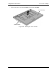
8. Secure the cover assembly with the following screws from the back and bottom of
computer.
• M2.5×4.0B FLAT BIND screw x3 ("4" in the figure)
• M2.5×6.0B FLAT BIND screw x3 ("6" in the figure)
• M2.5×8.0B FLAT BIND screw x4 ("8" in the figure)
• M2.5×16.0B FLAT BIND screw x10 ("16" in the figure)
4-38 QOSMIO G10 Maintenance Manual (960-497)