Rev 1.0 High‐Resolution CCD Color Camera MODEL CS6940CL Specifications Contents 1. Overview ...............................................................................1 2. Features .................................................................................1 3. Configuration ........................................................................1 4. Optional parts ........................................................................2 5. Specifications ........................................
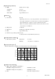
Rev 1.0 1. Overview This CCD color camera is a high-resolution color camera that features all pixel readout mode 1/1.8 CCD. 2. Features (1) High resolution Bayer array high pixel density CCD (number of effective pixels 2.01 M, number of total pixels 2.11 M) is used. (2) Square grids The CCD pixels arrayed in square grids facilitates computation for image processing.
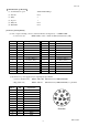
Rev 1.0 4. Optional parts (1) Power cable Model name: CPRC3700-** (2) Camera Link cable Model name: 14B26-SZLB-***-0LC (3) Camera adapter Model name: CA130C (4) Camera mounting kit Model name: CPT4000CL *NOTE: Application software is not supplied as a standard item. Notes on optional parts and compliance with safety standard conditions: We assure the compliance of this camera with the safety standard when it is used in combination with the optional parts listed above.
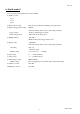
Rev 1.0 (13) Power supply voltage DC12 V ± 10% (ripple 50 mV(p-p) or less) (14) Power consumption Approximately 2.
Rev 1.0 [Output signal specification] (1) WEN DC IN connector output ・Signal level 4 V (p-p) ・Polarity Positive polarity ・Pulse width Approximately 53.3μs [Dimensions] (1) Lens mount C-mount *Depending on the lens you use, the performance of the camera may not be brought out fully due to the deterioration in resolution and brightness in the peripheral area, occurrence of a ghost, aberration and others.
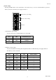
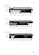
Rev 1.0 [Communication specification] (1) Communication speed 9600/19200/38400 bps (2) Data bit None (3) Parity 8 (4) Stop bit 1 (5) Parity bit None (6) Handshake None [Connector pin assignment] (1) Video output/controlling connector (Camera Link Base Configuration) ・Connector model Pin No. 1 2 3 4 5 6 7 8 9 10 11 12 13 I/O O O O O O I O I I I I - : MDR CAMERA LINK 26-PIN connector 10226-2210VE (manufactured by 3M).
Rev 1.0 [Switch setting] By using the DIP switches on the back surface of the camera body, you can set serial transmission speed and memory readout for when the power supply is turned on.
Rev 1.
Rev 1.
Rev 1.0 6. Serial control You can control following functions in camera link I/F. (1) Memory control ・Save ・Load ・Reset (2) Readout mode setting All pixel readout / Partial scan/ High-speed draft readout (3) Random trigger shutter setting ON/OFF * When the random shutter is active, AE setting is disabled.
Rev 1.0 7. Explanation of operation 7.1 Readout mode Video is output from the camera link connector. The output video can be grabbed by the frame grabber board.
Rev 1.0 2) Partial scan Skips the top and bottom of the effective area and reads out 552 lines in the center area in approximately 1/30 second.
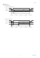
Rev 1.0 7.2 Random trigger shutter In the random trigger shutter mode, you can shoot and grab an image at an arbitrary timing by trigger signal input from the external. ・External trigger signals can be input either from the camera link I/F CC1 or DC IN connector. ・If polarity is set to negative polarity, exposure starts at the falling edge of the trigger. ・The random trigger shutter of this camera can be operated in two types of mode: fixed mode and pulse width mode.
Rev 1.0 7.3 Multiple-shutter mode In the multiple-shutter mode, video is output in sync with a MULTI signal from the external after the end of exposure time. ・Valid only when the random trigger shutter mode is ON. ・MULTI signals can be input from the camera link I/F CC2. ・If exposure is executed several times before MULTI signal input, the images are output superposed. ・The exposure time is determined by the random trigger shutter mode setting and its determination method.
Rev 1.0 8.
Rev 1.0 9. Cases for indemnity (Limited warranty) We shall be exempted from taking responsibility and held harmless for damage or losses incurred by the user in the following cases z In the case damage or losses are caused by fire, earthquake, or other acts of God, acts by a third party, deliberate or accidental misuse by the user, or use under extreme operating conditions.
Rev 1.0 Head Office : 7-1, 4 chome, Asahigaoka, Hino-shi, Tokyo, 191-0065, Japan (Overseas Sales Department) Phone : +81-42-589-8771 Fax : +81-42-589-8774 URL : http://www.toshiba-teli.co.jp Distributor • This product must be classified for disposal according to the laws of each country and municipal laws. • Information contained in this document is subject to change without prior notice.