
Operation Manual

6
WIJZI G I N GEN E N T YPE F O U TEN VOORB E H O UDEN
WIJZI G I N GEN E N T YPE F O U TEN VOORB E H O UDEN WIJZI G I N GEN E N T YPE F O U TEN VOORB E H O UDEN
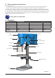
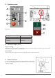
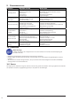
5. BedieningSpaneel
A: Toerentalindicator F: Waarschuwingslicht
B: Keuzeschakelaar boren/tappen G: Startknop
C: Snelheidsinstelling H: Spanningsindicatie
D: Noodstop I: Stopknop
E: Diepte-instelling
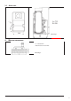
6. afStellen van de tafel
Hoogte verstelling
Om de tafel verticaal te verstellen, de klembout losdraaien, de tafel in de juiste positie brengen door aan de hendel
te draaien en de klembout weer stevig vastzetten.
360° draaibaar
Draai de klembout los en draai de tafel naar de gewenste positie, zet de klembout vast.
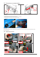
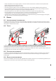
7. diepte inStellen
De diepte-instelling (B) bevindt zich bij de zijspindel. Maak de stelbout (A)
los en ga naar de juiste positie. Maak de stelbout weer vast en laat de spindel
terugkomen (afb. 5).
3-2.Operation illustration and procedure:
1. There are three T grooves in the worktable. It is used to fix the work piece.
1-1.There are two T grooves in the base, too. It is convenient for fixing the longer, heavier and larger
working piece.
OPTION
2. The pulley cover is strictly prohibited to open in normal operation condition.
3. Protect safety guard shall be allocated in a proper position in operation. It is controlled by a micro
witch. (For CE)
4. Adjustment of feeding limit
To prevent unwanted penetration to work piece, the feeding limit
shall be set by adjusting the appropriate position of feeding depth
fixing button as long as the distance between the end of tool and
top surface if work piece is measured.
A. Setting of feeding depth
1. Loosen knob A.
2. Turn scaled ring B to desired feeding depth.
3. Lock knob A.
15
Lock
Loose
Afbeelding 5
3-1. Control panel instruction:
A. min-1 or /min (R.P.M.) Indicator
B. Drill / Tap Switch
C. Speed Control Switch
D. Emergency Stop Button (For CE)
E. Feed Depth Adjustment
F. Fault Light
G. Start Button
H. Power Light
I. Stop Button
1. Check the power source
Push the start button to judge the motor and spindle shaft is in normal condition or not.
2. Spindle speed adjustment is controlled by the speed control switch. The speed will be
showed out in the electronic digital meter.
3. If it needs to stop urgently, just push the emergency stop switch.
4. Drill / Tap switch: For changing the machine to Drill Mode or Tap Mode.
9
Afbeelding 4