
User's Manual


User's Manual
2-2
TT
TT
T
HEHE
HEHE
HE
G G
G G
G
RANDRAND
RANDRAND
RAND
T T
T T
T
OUROUR
OUROUR
OUR
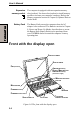
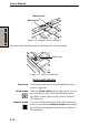
Display latch This latch secures the LCD panel in its closed position.
Push the latch to open the display.
Power source/ LEDs let you monitor the status of various computer
system indicators functions. Details are given in the Indicators section.
Battery lock This indicator shows the status of the Battery lock by
indicator color: red for unlocked and green for locked status
respectively.
Battery lock The battery lock prevents inadvertent release of the Battery
Pack.
Infrared port This infrared port is compatible with Infrared Data Associa-
tion (IrDA 1.1) standards. It enables cableless 4 Mbps,
1.152 Mbps, 115.2 kbps, 57.6 kbps, 38.4 kbps, 19.2 kbps or
9.6 kbps data transfer with IrDA 1.1 compatible external
devices.
Battery release
lever
Releasing the battery lock and sliding the Battery release
lever to the outside of the computer enables to remove
the battery from the computer.
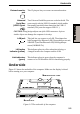
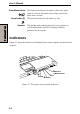
Figure 2-2 The left side of the computer
Figure 2-2 shows the computer’s left side.
Left side
SD CARD INDICATOR
SD CARD SLOT
WIRELESS
COMMUNICATION
SWITCH
MODEM JACK
(WITH COVER OPENED)
PC CARD SLOT
COMPACT FLASH
MODULE SLOT
Compact Flash This slot accommodates Compact Flash module of various
module slot capacities. You cannot use Compact Flash module that
does not conform to CFA specifications.
You can also use Compact Flash I/O module other than
memory module.
CAUTION: Keep foreign objects out of the Compact Flash module slot. A
pin or similar object can damage the computer’s circuitry.