
User Manual

103
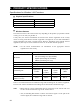
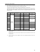
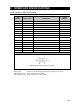
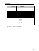
LAN Interface
Pin
Number
Signal name Explanation
Signal
Direction
1 TX Transmission data (+) O
2 –TX Transmission data (–) O
3 RX Reception data (+) I
4 Unused Not in use
5 Unused Not in use
6 –RX Reception data (–) I
7 Unused Not in use
8 Unused Not in use
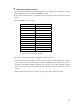
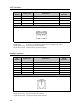
Connector diagram
Signal name: A minus (–) is attached to signals that are negative logic values.
Signal direction (I): Input to the personal computer.
Signal direction (O): Output from the personal computer.