
User Manual

102
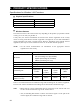
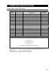
USB Interface
Pin
Number
Signal name Explanation
Signal
Direction
1VCC+5V
2 –Data Minus data I/O
3 +Data Plus data I/O
4 GND Signal ground
Connector diagram
Signal name: A minus (–) is attached to signals that are negative logic values.
Signal direction (I): Input to the personal computer.
Signal direction (O): Output from the personal computer.
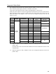
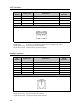
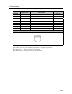
Modem Interface
Pin
Number
Signal name Explanation
Signal
Direction
1 — No contact
2 — No contact
3 TIP Telephone circuit I/O
4 RING Telephone circuit I/O
5 — No contact
6 — No contact
Connector diagram
Signal direction (I): Input to the personal computer.
Signal direction (O): Output from the personal computer.