
User Manual

101
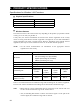
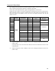
2. INTERFACE SPECIFICATIONS
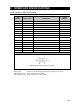
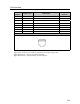
RGB Interface (Mini RGB Cable)
Pin
Number
Signal name Explanation
Signal
Direction
1 CRV Red video signal O
2 CGV Green video signal O
3 CBV Blue video signal O
4 Reserved Reserve
5 GND Signal ground
6 GND Signal ground
7 GND Signal ground
8 GND Signal ground
9 Reserved Reserve
10 GND Signal ground
11 Reserved Reserve
12 SDA SDA transmission signal I/O
13 -CHSYNC Horizontal synchronization signal O
14 -CVSYNC Vertical synchronization signal O
15 SCL SCL data clock signal I/O
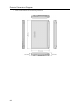
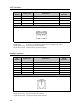
Connector diagram
High density D-SUB 3-row 15-pin male plug
Signal name: A minus (–) is attached to signals that are negative logic values.
Signal direction (I): Input to the personal computer.
Signal direction (O): Output from the personal computer.