
User Instructions
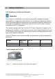
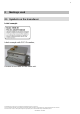
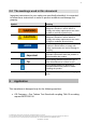
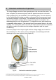
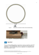
Table Of Contents
- 1 Safety Instructions
- 2 Markings used
- 3 Application
- 4 Structure and mode of operation
- 5 Mechanical installation
- 5.1 Important precautions during installation
- 5.2 Conditions on site
- 5.3 Installation orientation
- 5.4 Installation
- 5.5 Preparing for the rotor mounting (exemplary)
- 5.6 Mounting the rotor
- 5.7 Installing the telemetry system
- 5.7.1 Measuring setup
- 5.7.2 Instruction for installation
- 5.7.3 Calibration signal
- 5.7.4 Stator antenna
- 5.7.5 Evaluation unit
- 6 Electrical connection
- 7 Shunt signal
- 7 Functional testing
- 8 Maintenance
- 9 Dimensions of the stator antenna
- 10 Dimensions of the rotor antenna
- 11 Specifications

3
Geschäftsführung: Thomas Lippok & Jens Wiegand • Aufsichtsratsvorsitzender: Joseph Vorih
Sitz der Gesellschaft: Darmstadt • Als Gesellschaft mit beschränkter Haftung eingetragen im Handelsregister des Amtsgerichts Darmstadt unter HRB 1147
Unser Unternehmen ist bei der Stiftung Elektro-Altgeräte Register (EAR) unter der Nummer WEEE-Reg.-Nr. DE66485129 registriert.
CONFIDENTIAL - EXTERNAL
4 Structure and mode of operation
The torque flange consists of two separate parts: the rotor and the stator. The
rotor comprises the measuring body and the signal transmission elements.
Strain gauges (SGs) are installed on the measuring body. The rotor electron-
ics for transmitting the bridge excitation voltage and the measurement signal
are located centrally in the flange. The transmitter coils for contactless trans-
mission of excitation voltage and measurement signal are located on the
measuring body's outer circumference. The signals are sent and received by
a separable stator antenna. The antenna has to be mounted close to the rotor
antenna. The connection cable connects the stator antenna with the evaluation
unit which contains the electronics for voltage adaptation and the signal
conditioning.
Connector plugs for the torque signal and the voltage supply are located on
the evaluation unit. The stator antenna should be mounted tangential with
some gap to the rotor antenna (see chapter 5).
Fig 4.1: Mechanical construction in principle